I turned and added knobs to the piano front and smokebox door as well as fitting the locking handles. They are only little things but I perfected a technique where I could knock out a knob in 5 minutes so I made a couple extra for my friend’s G5 at the same time. The locking handles came from the spares box.


Next on the hit list was the vacuum ejector pipe or rather it was bending it to shape and making and fitting the nuts or slotted retaining rings that were designed to be tightened with a ‘C’ or hook spanner.
I have to confess that it took three attempts to get these to where I was happy with them. For the first attempt, I used a small slitting saw. Unfortunately, it was from a cheap set and the arbour that holds the blades isn’t a very good fit and therefore the blade doesn’t run very concentrically. This combined with trying to cut too many slits for the diameter of the rod basically ended up chewing a third of it away before I gave up.
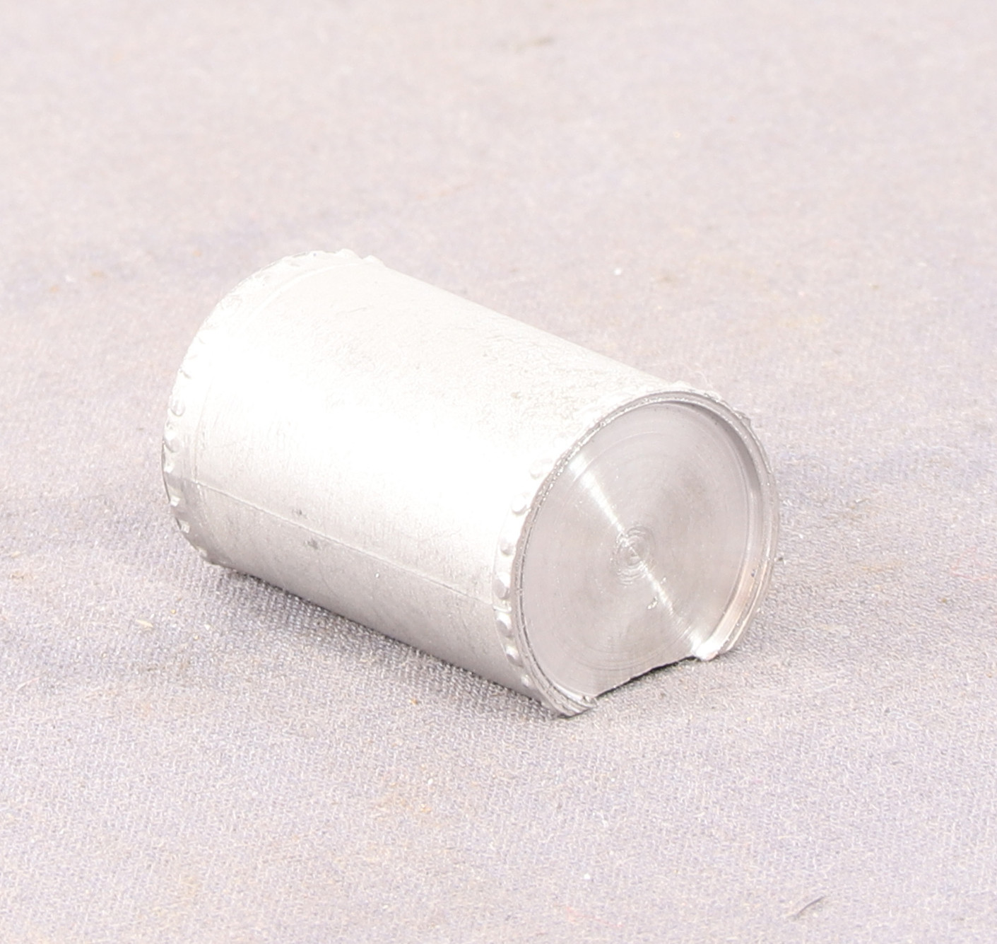
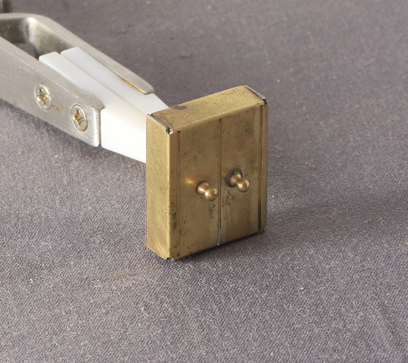
For the next attempt I kept things simple. I used a couple of pieces of bar with a couple of metric 123 blocks stacked on top of them to get me to the height of the brass bar held in the spin indexer collet. To make the grooves I used an Olfa cutter and reduced the grooves to six from the eight that I had tried on my first attempt.
![[IMG]](https://live.staticflickr.com/65535/55410975726_1a19b922f5_h.jpg)
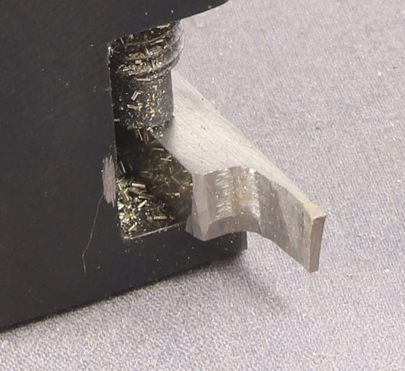
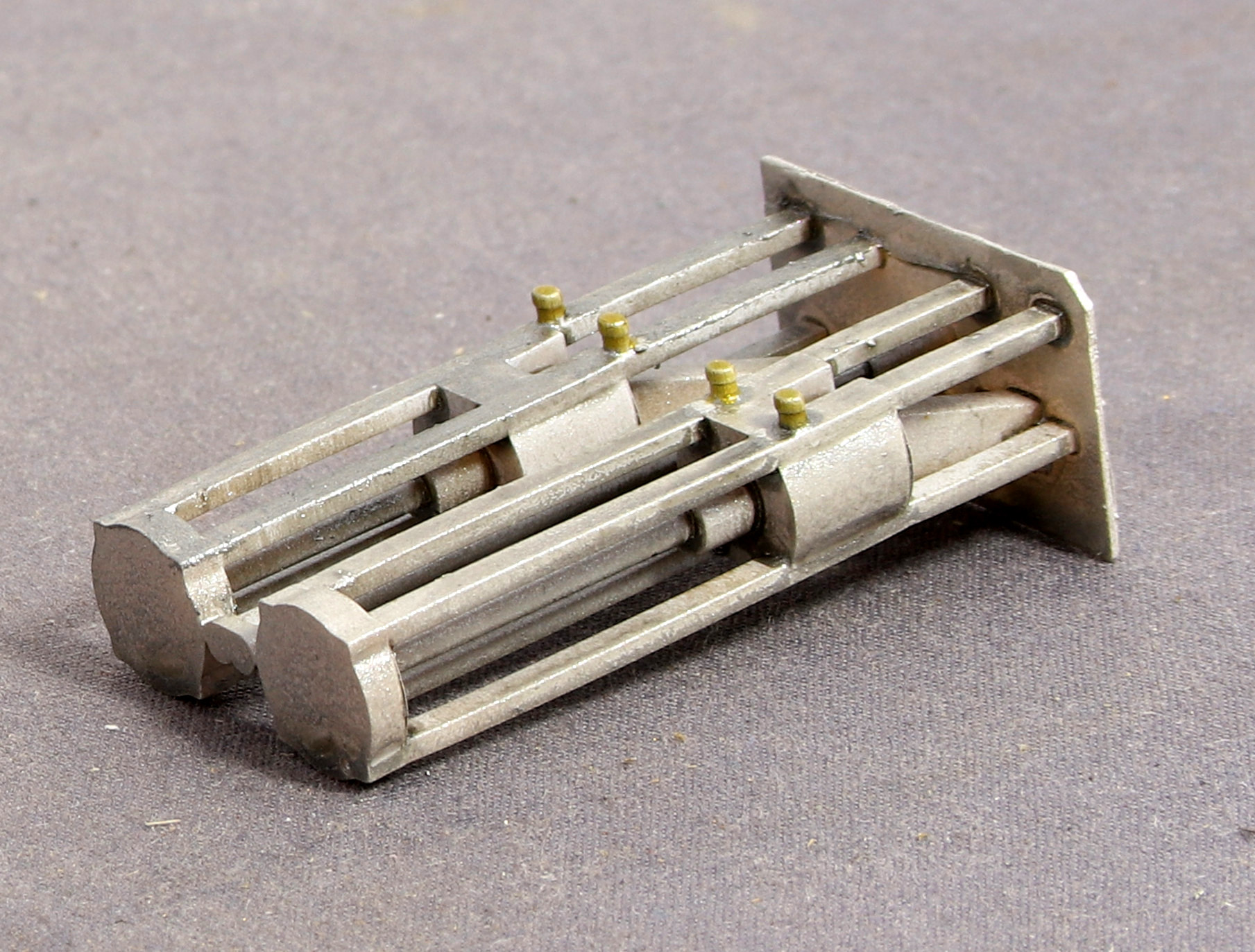
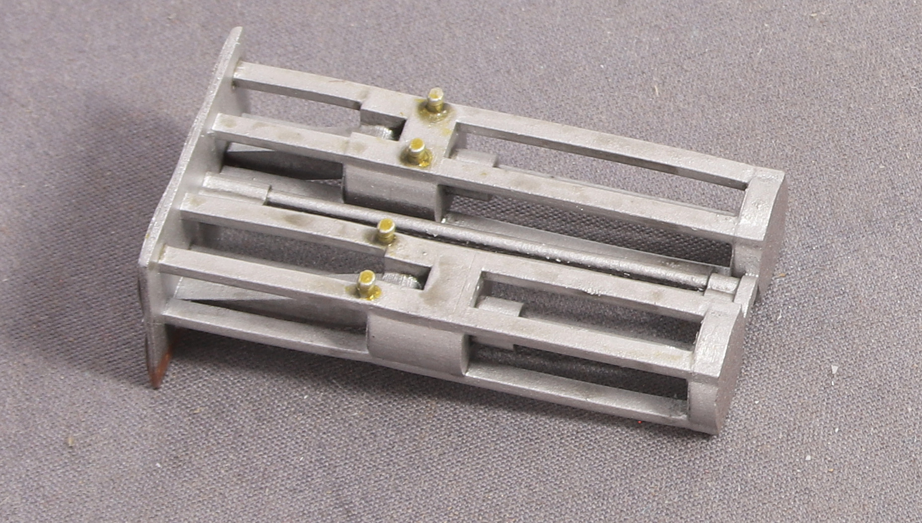
This worked but I wasn’t happy with the grooves, they were not defined enough. But having got the idea I thought about what I might have that would make a better- defined groove. The next thing that I tried was a carbide 60degree thread cutting tool. Which I lined up on the edge of the 123 block, and by carefully running the point of the tool against the brass rod. After a few passes, the slots were acceptable.


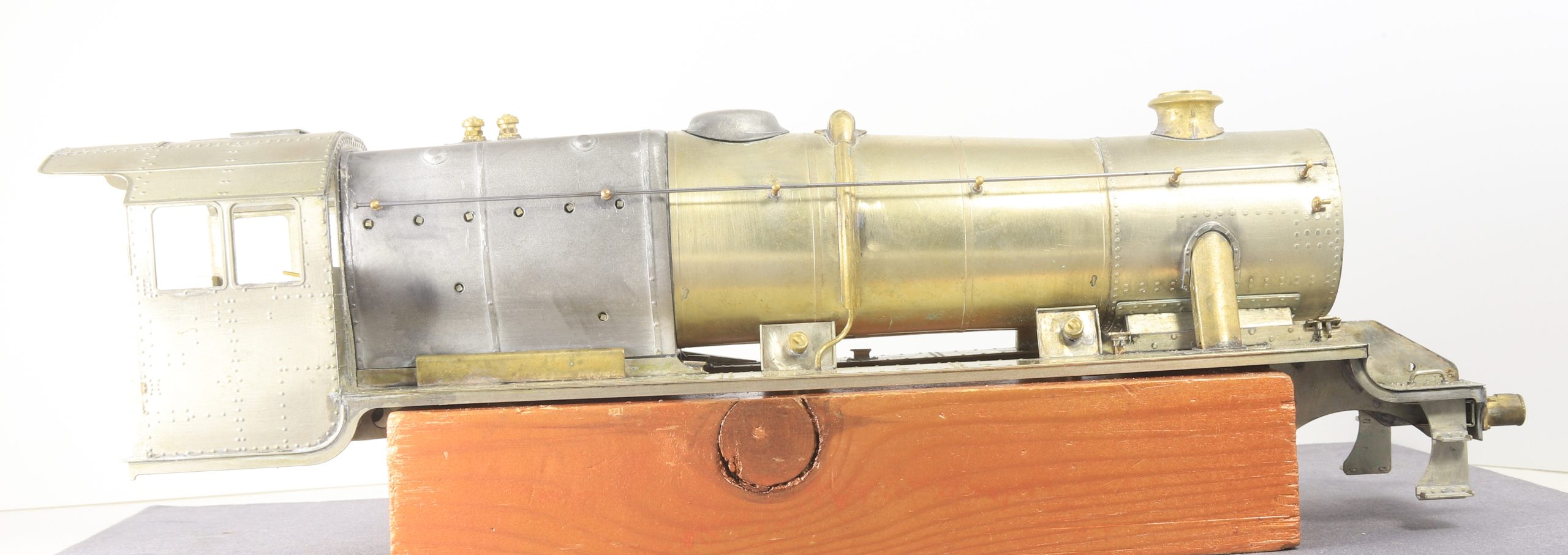
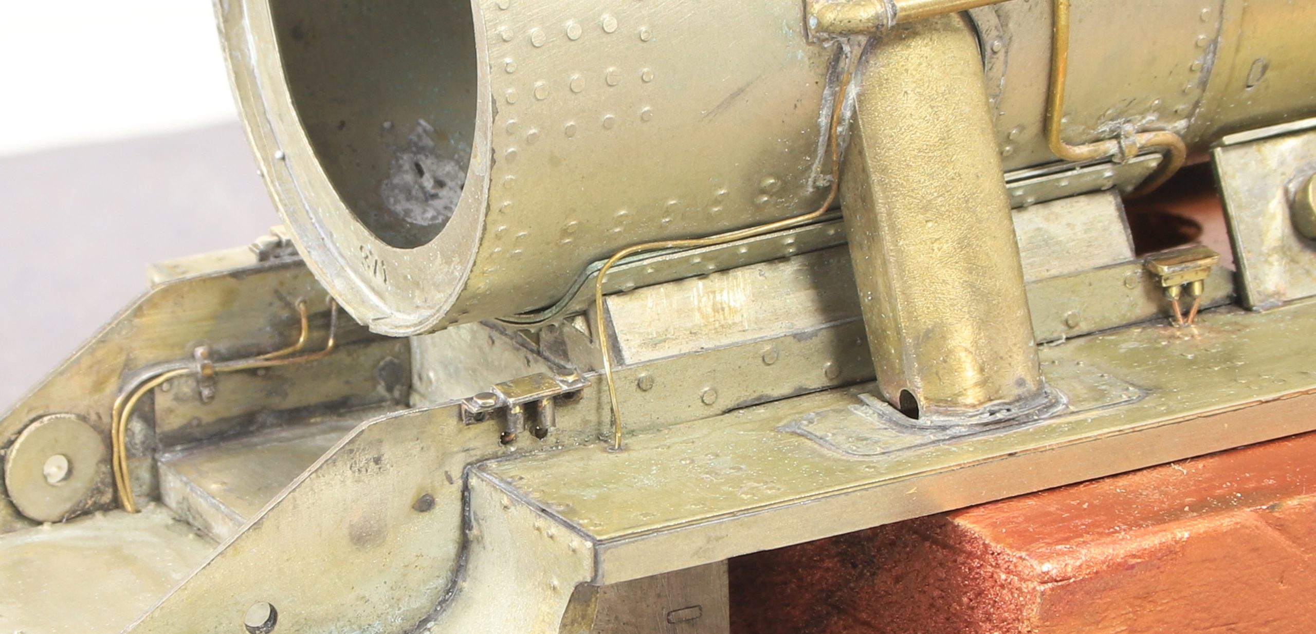
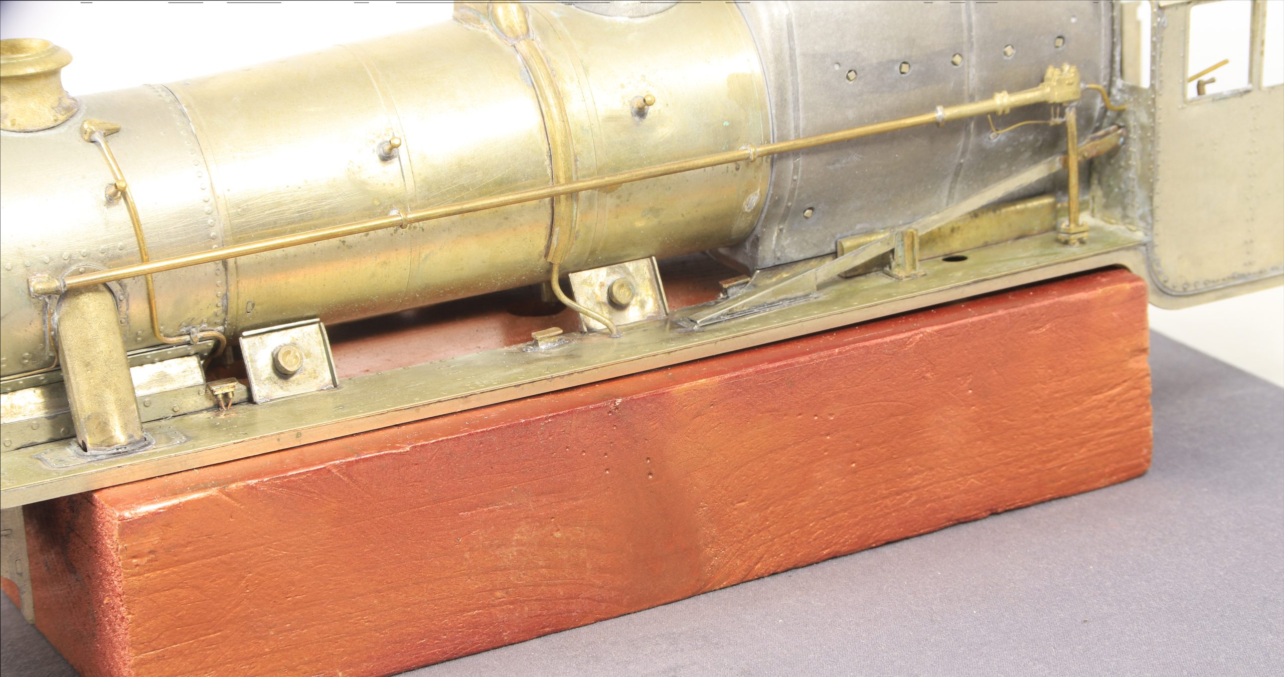
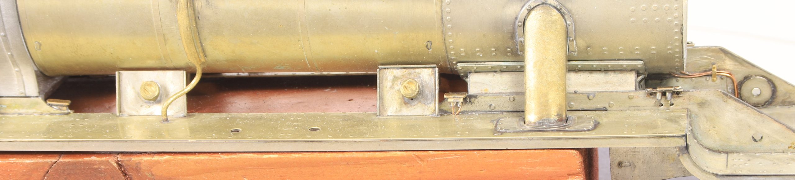
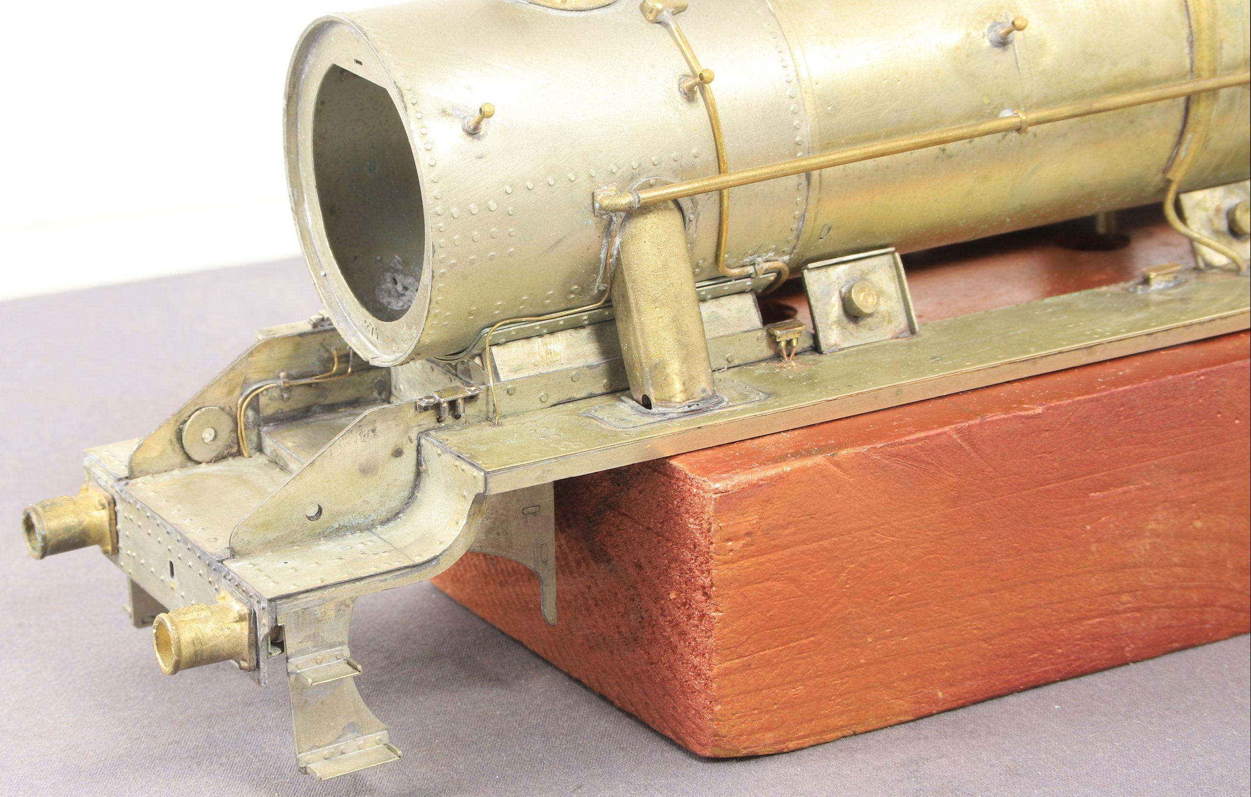
Here is the finished pipe complete with fittings and bent to shape but not fixed in place yet. I still have the Westinghouse pump and associated pipework to fit in front of the tank which might be easier if I can temporarily remove the vacuum ejector pipe

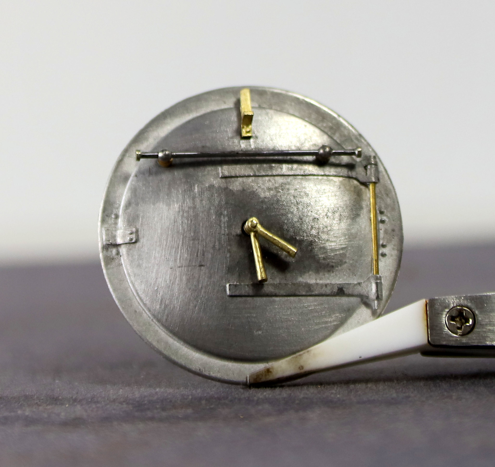
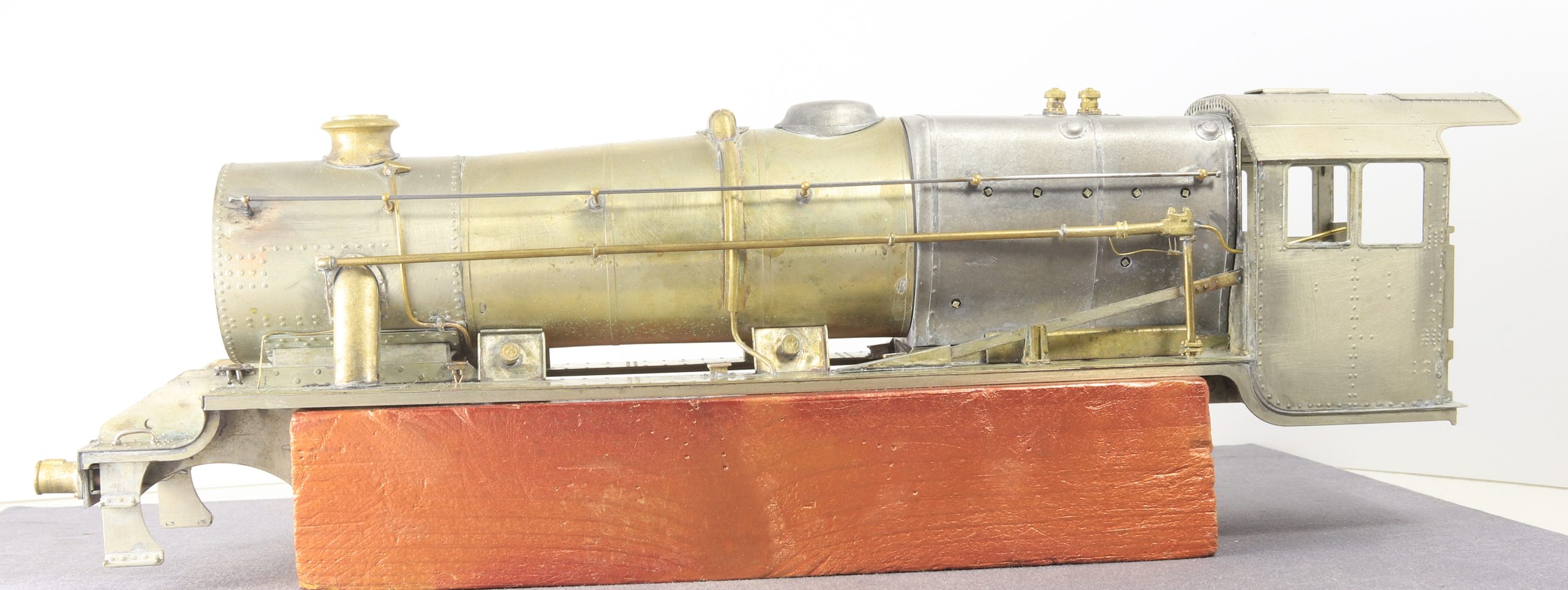
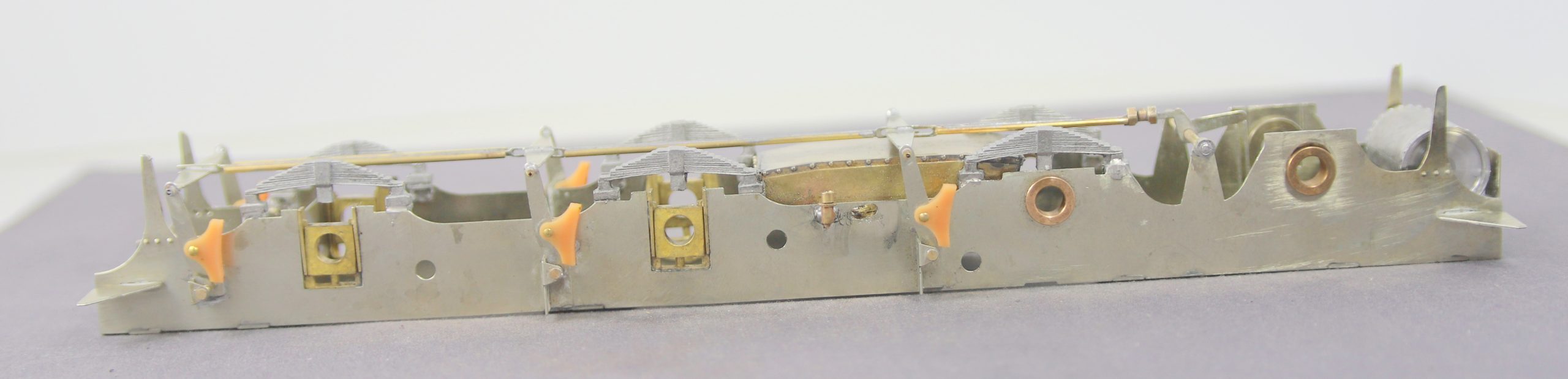
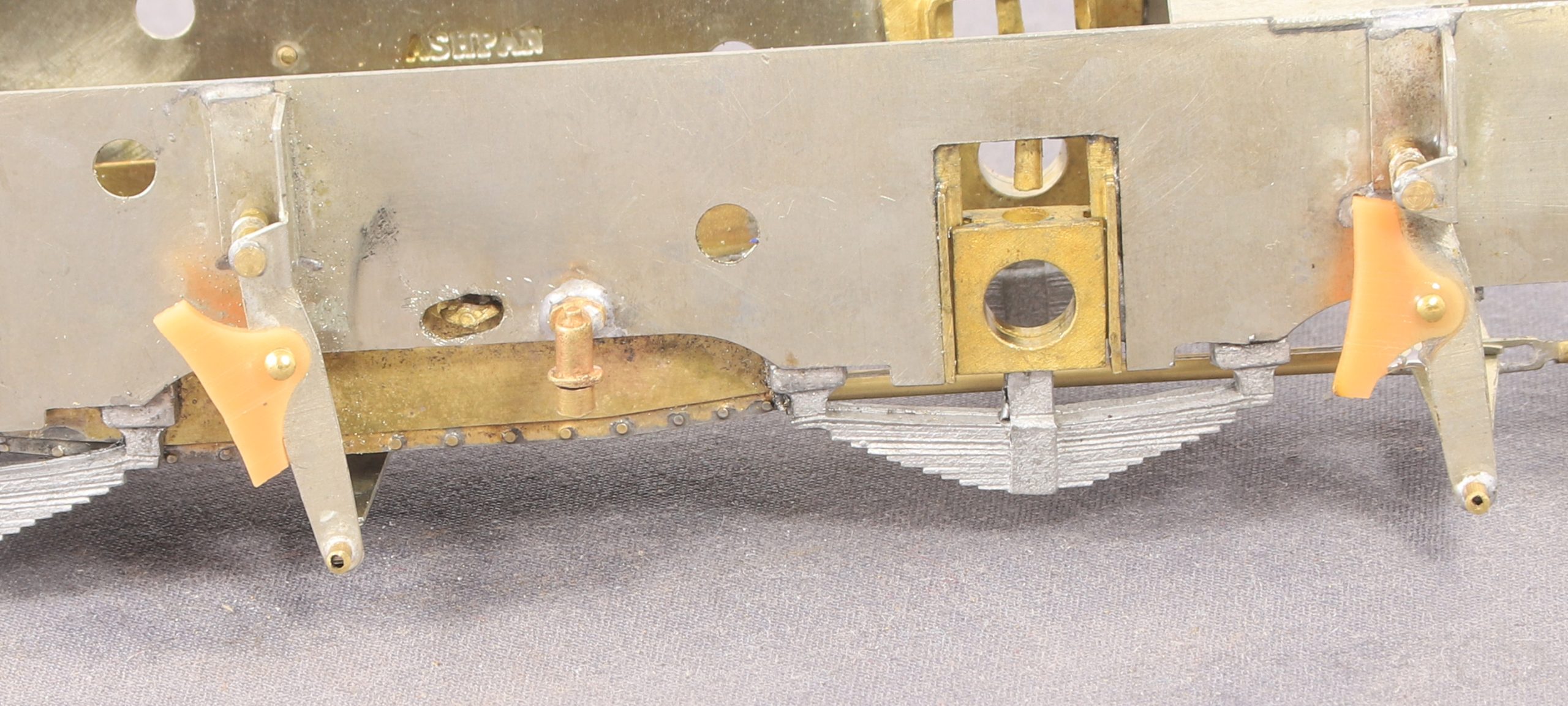
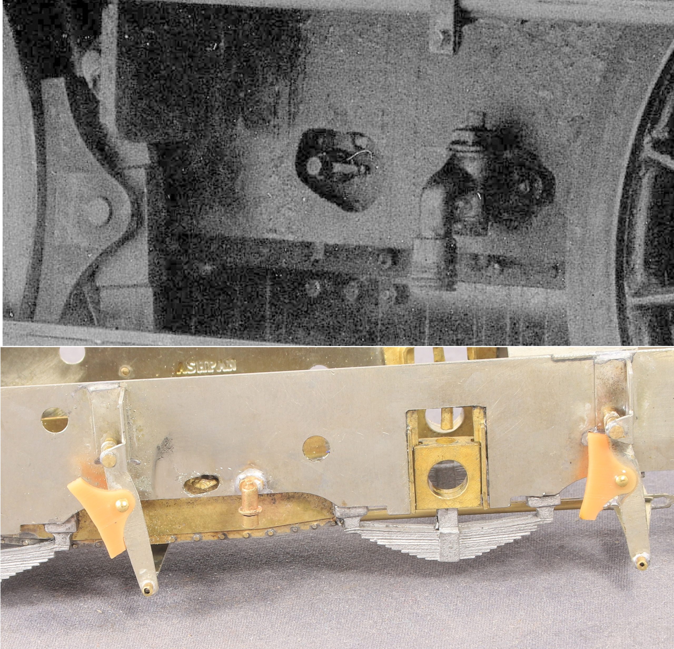
Finally (for now), as I’m returning to the 8F for a bit. Having looked at lot of photos, many of them show, one or both of the tank filler locking screws unclipped and dangling down. There isn’t much room to leave the right hand one dangle due o the Westinghouse pump and governor fitting so I took the left hand one off and refitted it the other way up and slightly bent outwards.

A small detail but it all adds to the fun.


![[IMG]](https://live.staticflickr.com/65535/55372407637_5e47d05c3b_h.jpg)