Newbould Models Gresley Restaurant Triplet Set

The NBR BG has been on hold for a while because I have been waiting for a friend to sort out a roof for it (who was in turn waiting for another friend etc.) I collected it at Telford earlier this month so I will progress that once the CCT leaves the bench.

In the meantime to wet appetites I thought that I would share another Telford acquisition which came quite out of the blue from a chance query.

Earlier in the year I bought a set of etches for a Gresley Restaurant triplet set from CPL and I was in discussions with both Rupert Brown and Peter Dobson about etches for the underframes and roof parts etc. I can get some of Rupert’s underframes from Wizard Models but Andrew needs to sort them out and Peter Dobson although having wound up newbould models as a business is still supplying bits and pieces and had done a test etch for the underframes but had never progressed them. I had arranged with Peter to bring some Gresley bogies to Telford for my CPL set and he said would I like to see his test etch underframes to which I said certainly.

It turned out that not only had he done a test etch for the underframes but also for the bodies as well but he had taken them so far an then popped them aside. Having had a look at them I asked since he hadn’t touched them for quite some time, if he would sell them ‘as is’ and a deal was struck.

This is what I got for the money:

IMG_6903 IMG_6904 IMG_6905 IMG_6906 IMG_6907 IMG_6908 IMG_6909 IMG_6910

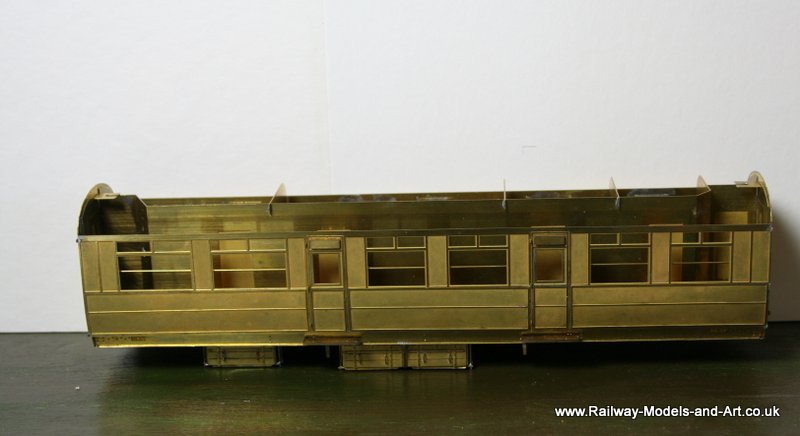
Also included were the remaining partitions for the restaurant cars and some etched tables. And hidden away under the tissue paper in one of the boxes was a very nicely finished Kemilway roof – so now I know what they should look like and can be made to look like…. note to self must try harder!

Connoisseur NBR Tender Truck Part 2

Two evening’s modelling on the trot sees moe progress made.

The body is well on it’s and is now quite a heavy and sturdy unit.

IMG_6543 IMG_6544 IMG_6546

I added the steps and dug out the etched LNER plates that Brian, a kind RMWebber let me have.

The ends, like the body sides are made up from 2 layers and the outer one has holes for pins that hold the cast end stanchions in place.

Soldering them in before adding the inner layer has made them quite secure – the use of some judicious heat sinks should see the ends attached to the body without them coming adrift.

The proof of the pudding…

I took the A3 along to the O Gauge North West show at Leigh today for a run on the test track.

The optimistic gents on the test track hitched her up to 44 wagons and she sailed away beautifully. Quite surprisingly they let me run her for around half an hour or so (I had expected a few laps at best). So I came away with a much inflated chest.

Fox Bogies

Once the sides were on the D176 I turned my attention to the bogies – yes I know that I need the underframe but there is method in my madness honest!

I need some Fox bogies for the BG and I have in the stash several sets of Newbould model Fox bogies (they are desdtined for other things but can be borrowed in the interim…).

The things about the Newbould bogies is that nice as they are there are no instructions so I had the lightbulb moment of building a set of Kemilway and a set of Newbould in tandem so that I could cross reference parts to get an idea of how the Newbould ones go together.

Below are a couple of photos of where I got to. – All is done to this point without any soldering on either pair of bogies.

IMG_5563 (800x406)
First up the Kemilway version. They gave the first time that I have had to do any amount of filing, which was needed on the front and rear of the frames. To be fair the instructions do point out that you will need to make them fit properly.

IMG_5564 (800x402)
Then the Newbould version.

So far they are similar in many respects.


A moment that I was dreading….

Not much has been happening on the workbench of late due to DIY/Gardening and general lack of Mojo :0(

One of this things that has been done is one of those things that I was dreading and which when I finally plucked up the courage to have a go at it went very smoothly and easily.

What I was dreading was soldering the two pieces together in between the whitemetal fingers.

LNER A3 Papyrus 001 LNER A3 Papyrus 002 LNER A3 Papyrus 004
How I achieved it was:
I fastened both arms to the links to the rods together with the 16ba nut and bolt provided. The ends of each are half thickness to create a lap joint. I then bolted one end to the frame spacer and held the two half lapped ends together with a pair of cranked locking tweezers.
Next using a tip that I picked up on one of Richard Lambert’s threads I cut some strips of kitchen paper and folded them so that they would fit down either side of the area to be soldered and wet them with a pipette after using tweezers to position them. Once the whitemetal at both sides was suitably protected, flux was applied to the joint; a quick in and out with the soldering iron tinned with 145 degree solder and the job was done.

Hopefully the 3 photos show the various positions as the valve gear moves.

Details from scrap etch…

Following on from a request on another forum for details of how to make the vac pipes I thought I would share these.

While up at the cottage last, I put together a Slaters 8 ton Midland van. It was a kit that I picked up 2nd hand and when I got to them I realised that the castings for door handles/hasp and staples were missing. I had the vague idea that I had some plastic ones left over from another kit but a search amongst the spares boxes didn’t turn them up.

I thought about ordering some from Slaters while kicking myself because I had just had a delivery from them of some of the fine chain that MMP use in their kits (an email to David P kindly revealed the source). Having just finished making up the pipes posted earlier today I decided to have a go at making some myself. A look in Midland Wagons Vol 1 gave me a decent photo of what they looked like and this is how far I have got.

First I got a length of 0.8mm wire and flattened one end in a pair of pliers. I then drilled a 0.3mm hole in the flattened section and doing the same through the dimple in the van door used this as the datum to determine the length. I drilled a second hole and soldered in 2 pieces of 0.3mm brass wire one of these I left long to go through the door to locate it and the other I filed flush. I then filed the 2 front pieces to represent the bolt heads on the face of the handle.

Having determined the length I cut it and flattened the other end again drilling 2 holes but a bit closer together. I bent a piece of 0.3mm wire into a U shape and fed it through the holes to make the staple for the pin or padlock. Again after soldering I left one end long and filed the other flush.

I did a similar exercise to create the vertical handles

Giving these – the handle has only been drilled on one end in this shot.

Midland 8 ton van 003

Fitting it to the van side looks like this. The brake lever and guard are from Bill Bedford via Eileens Emporium.

Midland 8 ton van 005

And both fitted on the other side.

Midland 8 ton van 004

Next up now I have my Mojo back is to make the hasp part. The plan is to make one closed and one open. Details to follow once I have worked out how to do it – more scrap etch to the rescue me thinks.


Home Brewed Vacuum Pipes

Due to other distractions (including updating the website) and general lack of Mojo I haven’t done much modelling for a couple of weeks.

I did spend a couple of evenings on these though.

Home brewed Vac Pipes 800

They are replacements for the whitemetal pipes that are supplied with their kits by Parkside. They look nice enough but I find them a bit vulnerable.

So some 1mm rod, some 28 gauge brass beading wire and some of the infamous scrap etch and we have these – apologies for the not too cracking photo. This was the second attempt and at that I gave up.

A bit like wheel blackening, I find making these up to be very therapeutic.

Through the paint shops

I recently changed the filters in my spray booth after putting it off for far too long. It won’t come as a suprise that it was a much easier job than I had built it up to be in my mind. Having done that I made a start on my backlog of stock ready for painting.

First up is a Slaters MR open wagon. I picked this kit up cheap from the bring and buy at the GOG Halifax show. I added internal detail to it from plastic strip as I built it but otherwise it’s straight from the very ancient box…

A lick of paint 001 A lick of paint 002 A lick of paint 003 A lick of paint 004 A lick of paint 005 A lick of paint 006

Support and Guidance, if you will for give the pun…

I spent yesterday and part of today putting together the support frames/guide wheels that allow the bridge to rotate. This has been the hardest bit of the build so far and that wasn’t hard so much as fiddly. It took a few goes to get the end U sections soldered square across the I beams with the right width at either end and that’s despite having a template to bolt across it. The instructions suggest assembling this on a piece of glass which I did I still ended up stripping the wheels/bearings back of one of these to give it a further rub down to ensure that the guide wheels rotate freely.

Then most fiddly of all was getting all the 16ba screws/nuts on – all 48 of them. The instructions suggest having the nuts uppermost as being most prototypical.

How I managed this was to feed a couple of 16ba screws through from below. I used some short pieces of coffee stirrer wedged in to hold them in place while I fit the brass bearing in place over it. You need to be careful that you pair these up correctly of they don’t fit – guess who had to take some of and start again to discover this……

Not having any 16ba nut runners I folded a loop on a piece of brass wire that passed through the nut. I used this to pick up and place the nut and then prodded,/tightened the nut onto the protruding thread with a cocktail stick finally tightening with a pair of pliers.

Which gave me these.

I also managed to get all the handrail/walkway support brackets folded and soldered up. The next job is to clean up all the cast brass handrail pillars and then open out the holes in the brackets to accept these.

The clear plastic plates are to insulate the guide wheels from the bridge

The Beauty of MOK kits

In between fiddling about with the valve gear I have also made up the front of the frames. At this point only the laminates of the frame extensions/lifting rings and the frames/cages that support the back of the buffers are soldered. All the rest is just held together with the slots and tabs. It really does make it easy when it all fits as it should and it is self supporting while you apply the solder.