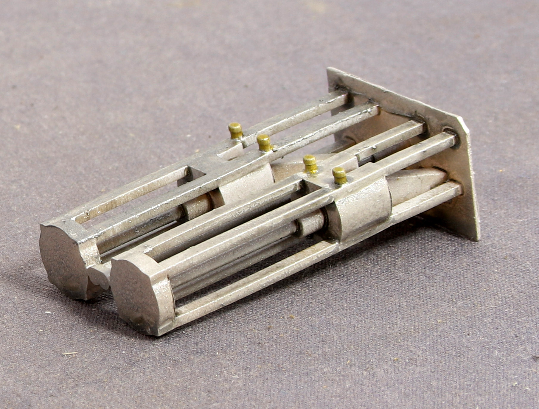
Not having much time yesterday, I decided to put a top coat on a couple of the inside motion sets to see what looked like. When priming I had done the first set in light grey but the detail could barely be seen so I switched to red oxide.
With the top coats, I sprayed the grey primer with Vallejo Oily Steel (I initially tried brush painting it but that wasn’t going to work) let down with screen wash and the red primer with Vallejo Model Air Silver with a small blob of Vallejo German ‘Cammo’ Black-Brown mixed in. Both were then washed after drying with a wash of Vallejo Charred Brown.
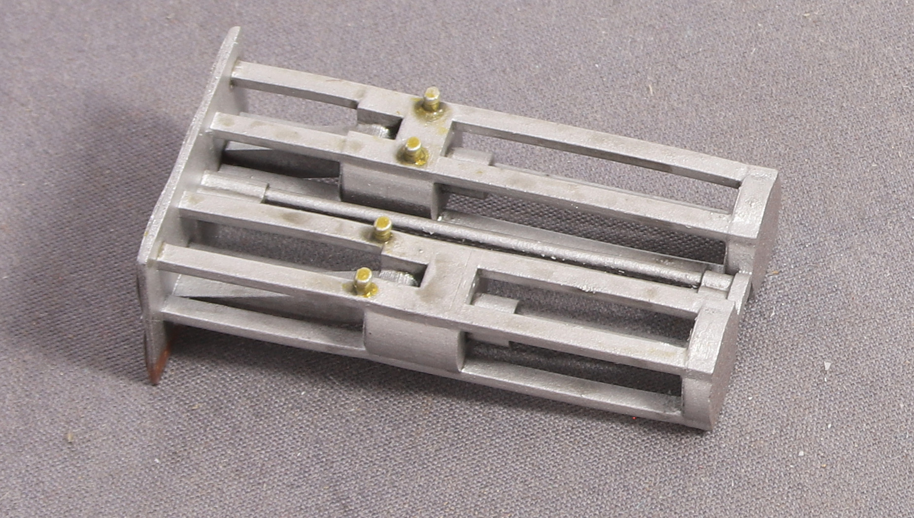
Grey Primer

Red Primer

In fairness, the ‘Oily Steel’ coat didn’t really need much in the way of further weathering from the wash. But the Vallejo Model Air Silver was much easier to spray.
I’m going to try some further tests using a black primer.