This is a blog where I will show the trials and tribulations of model builds as they happen
Category Archives: MOK 8F 8425
The build of an MOK LMS 8F kit. The aim of the build is to represent 8425 one of the class built by the GWR for the War Office and subsequently passed back to the LMS.
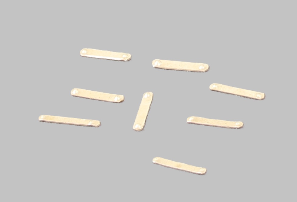
Although much of my recent modelling time has been spent on the N10 the 8F hasn’t been entirely neglected. I did manage to get the GWR esque lam irons fitted to the front of the loco.
The 3D printed Silvertown Lubricators have now arrived so I will be making a start on piping them up.
Still working away on detailing the loco body, while awaiting the lubricators I decided to fit the handrails Oridinarily I would fit the hand rails last but with LMS engines having small finials on each end of the hand rails I thought it prudent to do them before paint so that when I fit and file them back I don’t damage the paint work.
I started with the smoke box door and fitted both the handrail and the lamp iron.
The finials (or whatever they’re actually called) are made from 1.4mm nickel rod drilled out .8mm to accept the 0.8mm piano wire which I use for the handrails. They are soldered on to one end of the hand rail and filed back to size the handrail is then fed through the handrail knobs via the cab and having cut the piano wire to length the second finial is soldered on and again carefully filed back.
From the photo it looks like the left hand, handrail rises up slightly at the front. I had to resolder this end knob in as it has loosened during fitting. So I will revisit it to make sure that’s it’s aligned better.
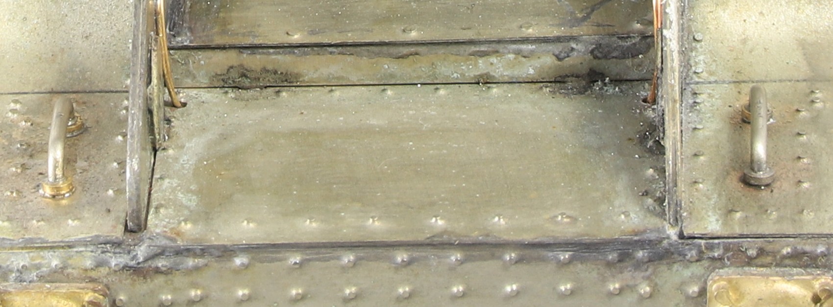
Finally yesterday I made and fitted the two small grab rails on the dropped section of footplate.
In some of the photo that I have these grab handles have small washers around the base of the rods. These were turned from 1.6mm rod drilled to accept the rod and parted off at 0.5mm thickness
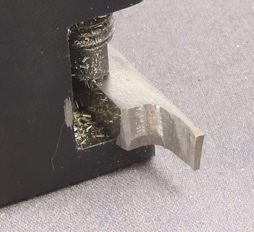
As and aside, due to the lack of rigidity in something as small as 1.6mm a normal 1/8″ or thinner metric 2mm parting tool still exerts a lot of tool pressure meaning that the work piece is more likely to bend than part of. To get around this I ground up a very thin parting tool which is excellent for parting thinner material.
The cutting tip of the tool is only 0.8mm thick so tool pressure is greatly reduced
I also ground it to the left hand side of the tool meaning that I can get very close to the chuck which reduces stick out and increases rigidity.
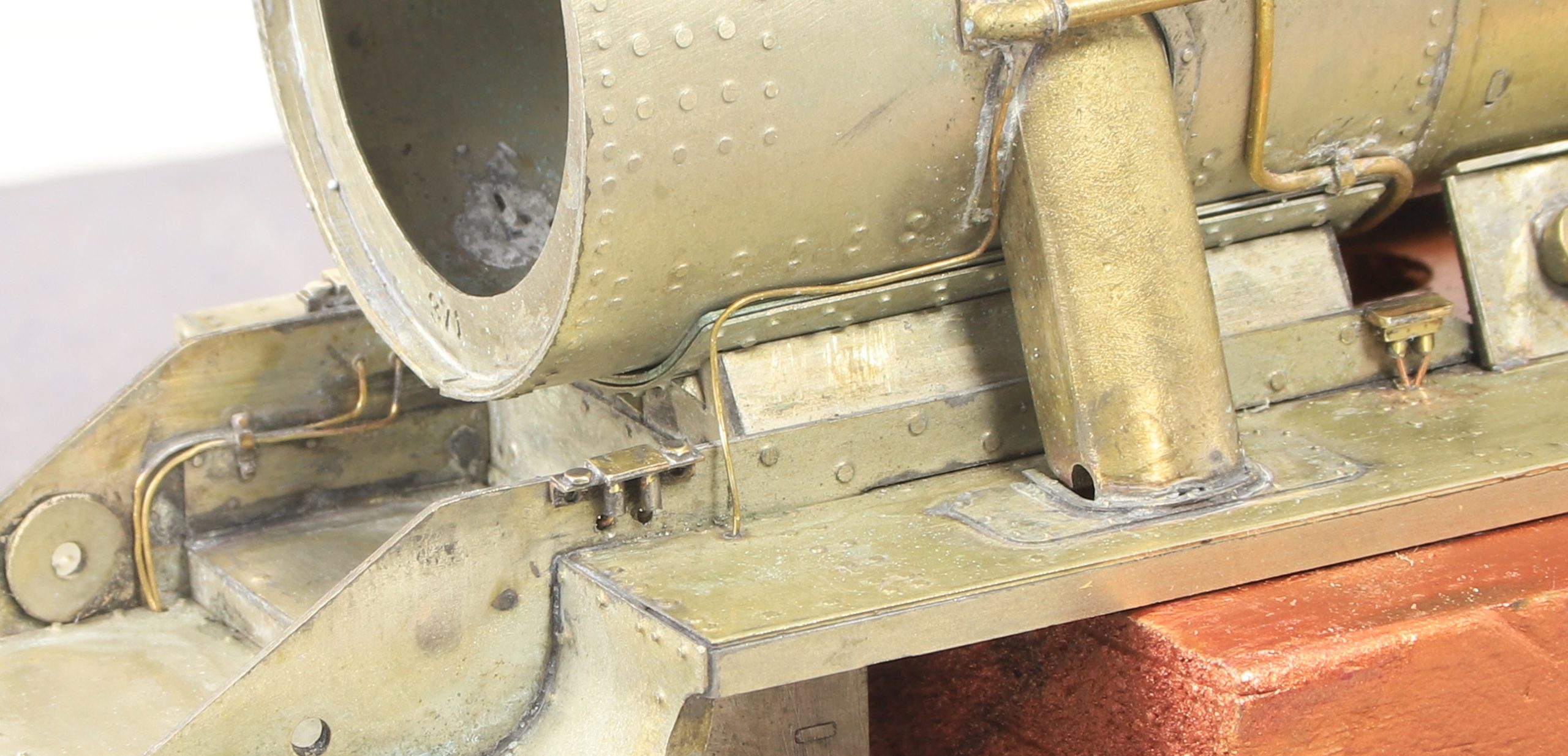
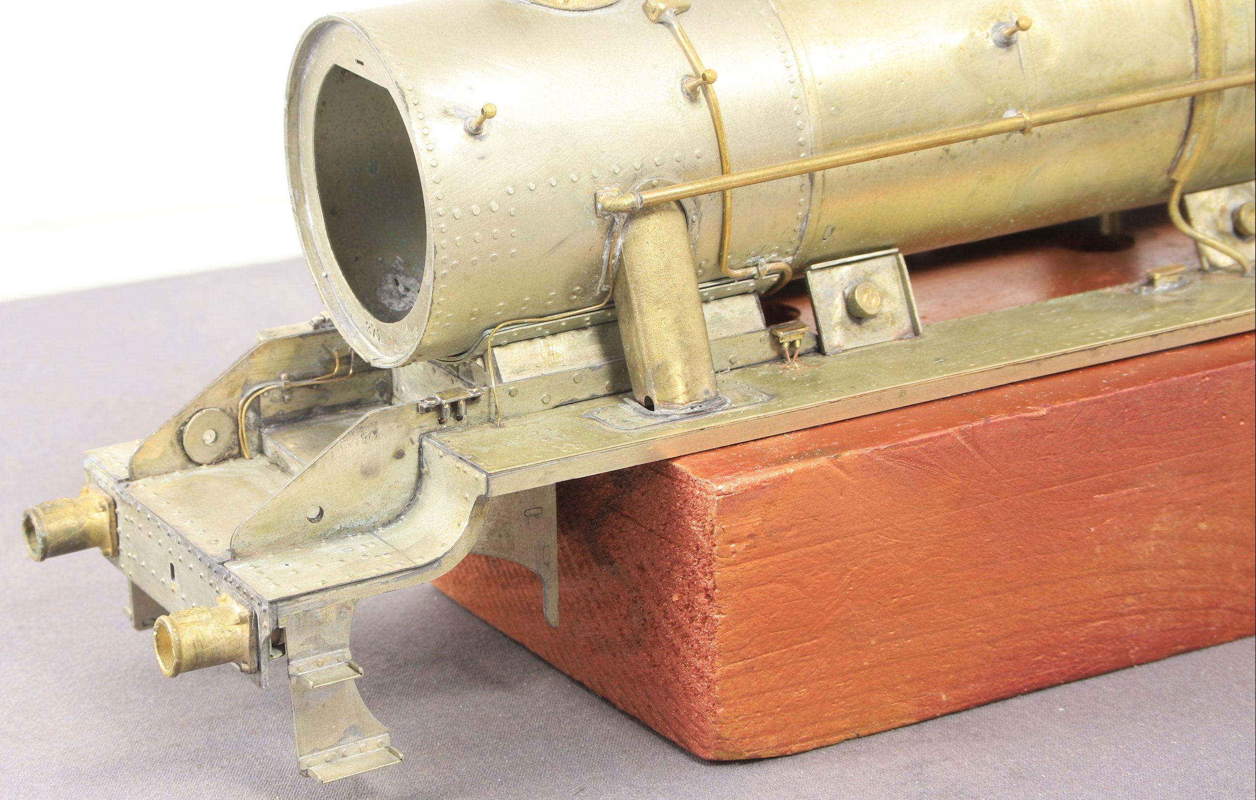
After several sessions at them I finally have all the oil boxes on the footplate aside from the large Silvertown types on the right hand side of the locomotive – they are the next job.
I started with the ones at the front which needed the associated pipework down inside the front of the frames under the smokebox. Again I made use of the Finney cable clip etches.
Then I fitted the ones that sit flat on the footplate including those that sit just inside the frames in front of the firebox. Lastly I fitted the ones at the rear of the smokebox that have pipes passing through the footplate.
Finally I did the two that initially, I thought sat at the inside of the footplate. However upon closer inspection, they actually sit on a bracket mounted to the inside of the frames.
Having made them I figured it made sense to fit them before fitting other more vulnerable bits.
Not sure why since I have been concentrating on the left side of the loco so far but I started on the right hand side.
All went according to plan
Not so, on the left hand side. I can only assume that the wall thickness of the firebox castings is thinner on this side.
I couldn’t live with them as is so I had a choice attempt to file them down or remake them a bit shorter and put the longer ones in the spares box. Since I was still pretty much set up to make more, I elected for the latter.
Even with doing a test example to check that I had made the correct adjustments to my measurements it still took less than half an hour to make enough for the right hand side.
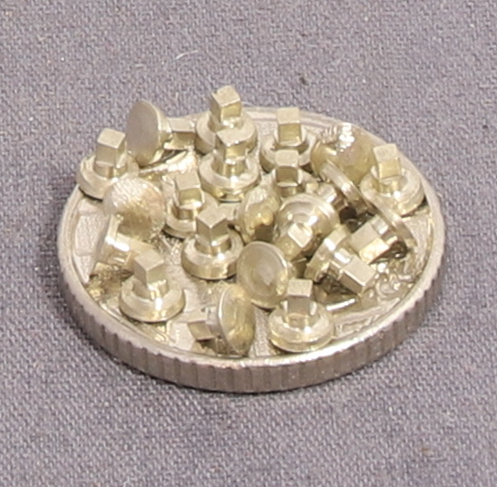
While still set up for making washout plugs and having looked through a few of my other kits to see if I need any more at some point (which I do). I decided to see how many I could make in 45 minutes.
I was pleased and a little surprised that I managed to make a dozen. Now compared to commercial CNC machined offerings that would be quite pitiful.
However when you consider that you have to turn the spigot on each end of the bar, then transfer it to the spin indexer to mill the square section. Then back to the lathe for parting off and turning the next spigot.
When using a collet block the work has to be backed out quite a long way to clear the cutter and the machine switched off to remove risk of injury while indexing the collet block. My collet blocks (ER25) are quite nose heavy due to the big collet nut on the end. This makes it essential to make sure that you have it pressed flat in the vice before tightening it. If you relax that pressure for the slightest instant before the vice grips it will tilt forward and throw the job out of kilter.
With the spin indexer you can literally move the cutter a couple of mm away from the work piece and unscrew the lock, then remove the indexing pin before rotating to the next index position, with your hands well clear of the cutter. Which means that not only do you not have to make many turns of the hand wheel to clear the workpiece, but you can also leave the machine running during reindexing and that saves so much time.
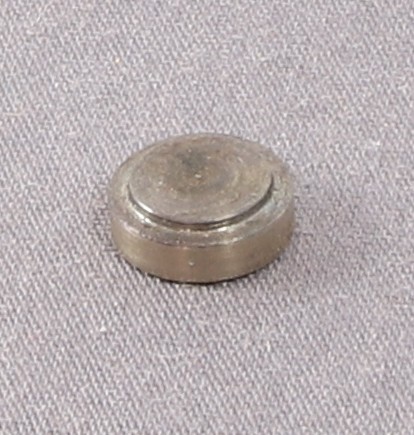
I was asked very tongue in cheek whether all the washout plugs that I made would fit on my 5p piece. I’m sad enough to try them and the answer is “yes they do”!
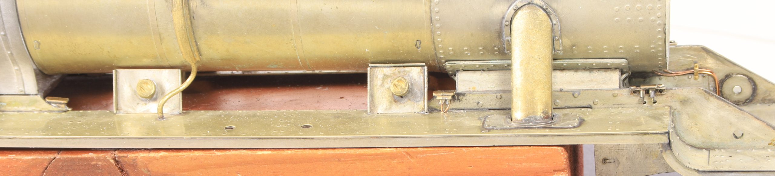
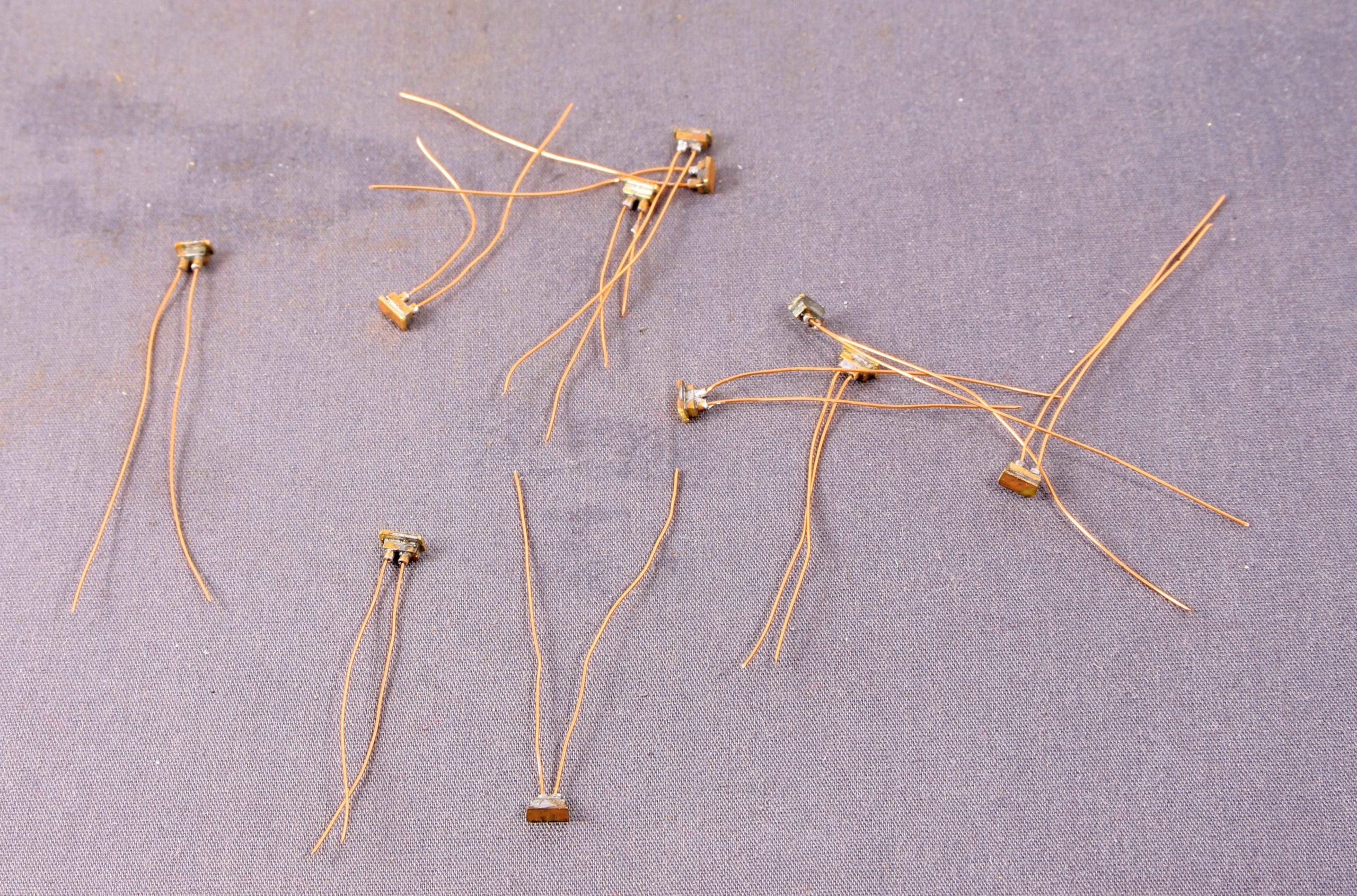
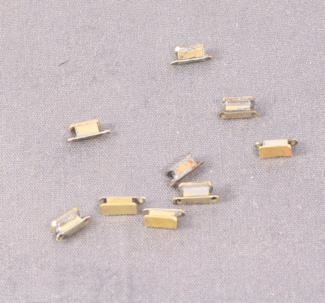
Studying photos shows that there are quite a number of 2 port oil boxes dotted about the footplate and visible inside the upper frames. There were some castings provided but there were only four of them and they lack mounting plates. While I could and did make mounting plates I also elected to remake the oil boxes with a bit more detail.
Besides to large 6/8 port lubricators mounton the the right hand side there seem to be three different types of 2 port lubricators so i have replicated each type as best I can.
The types that I have identified (so far) are:
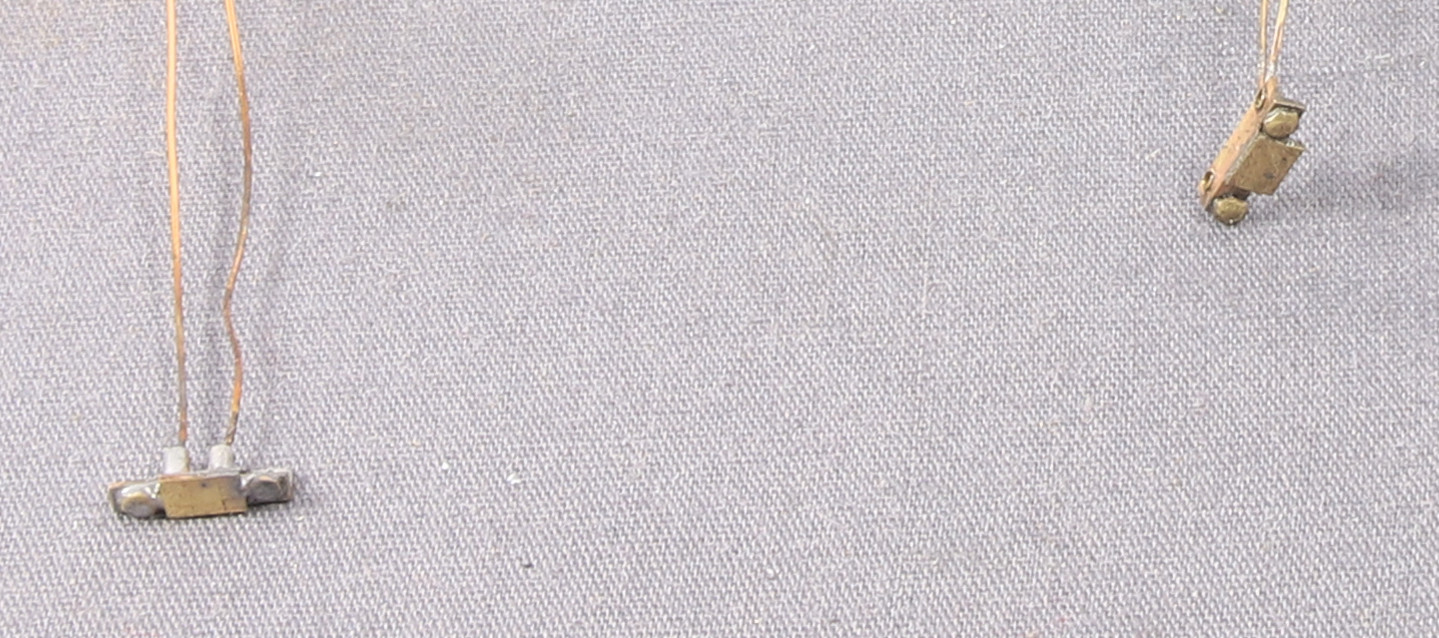
Rear mounted with pipes coming out of the bottom.
2 Port Lubricator Boxes
Bottom Mounted presumably with the pipes also coming out of the bottom, but I haven’t modelled them.
The last type are those mounted at the front of the frames just under the end of the smokebox. These are very shallow and have a couple of prominent mounting nuts on top of the angle iron mounting plate.
What can’t really be seen in the photos is that back edge of the angle plate also has two holes and after struggling to workout how I might hold all the other parts together while I added the last two mounting bolts (the brass angle doesn’t take pressed rivets very well due to the proximity of the other leg) I elected to use the holes to drill the frames and then pass brass pins through to mount them.
After doing the initial rear mounted boxes with 180 degree solder it occurred to me, that I would make life much easier, if I soldered the others together using 296 degree solder. Thus making it less likely that they would fall apart if soldered to the frames with 145 degree solder. time will tell.
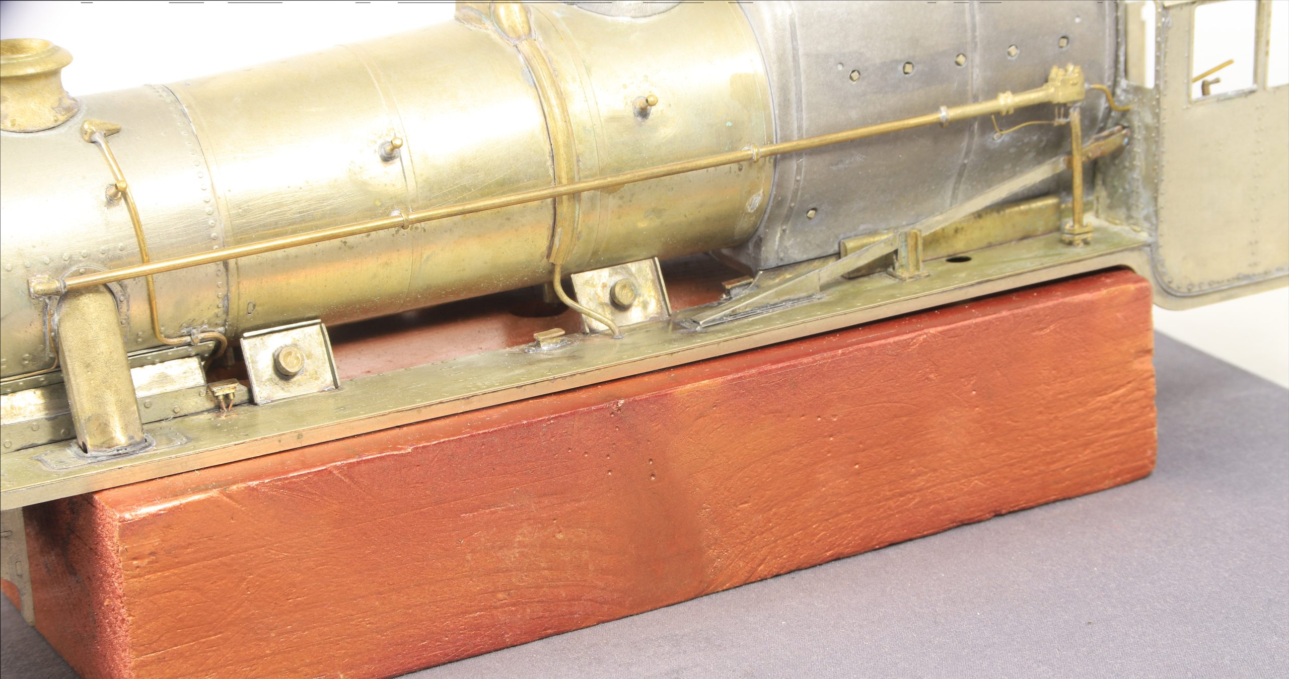
Still working away at adding details to the left hand side of the loco (although, I have added the solid blocks to the base of the firebox on either side).
After much fiddling to get the vacuum ejector pipe to sit horizontal I got there and it’s now fixed in place. As happens sometimes. I spent some time making the very visible pipe flanges that are fitted to the lower section of the vacuum pipe just above the footplate.
The best of these were soldered together in pairs and one pair fitted to the pipe. Then of course I discovered a pair of nice castings on a spru so my homemade ones are consigned to the spares box for now.
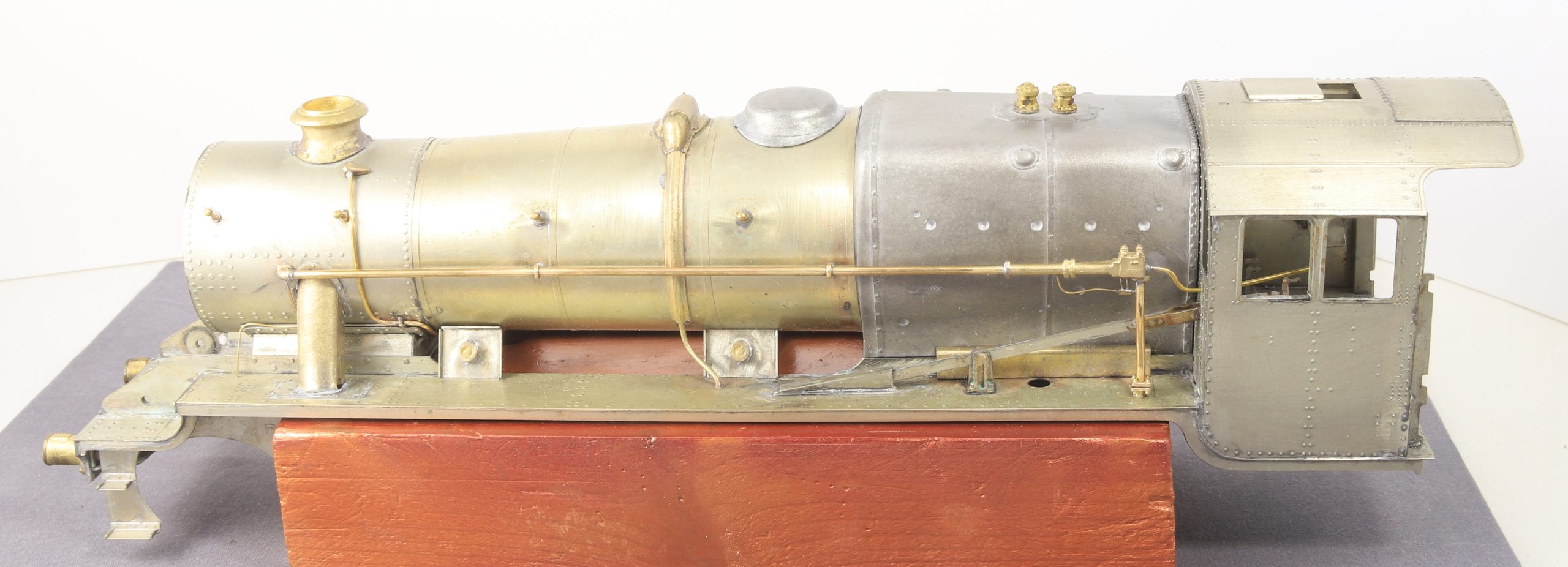
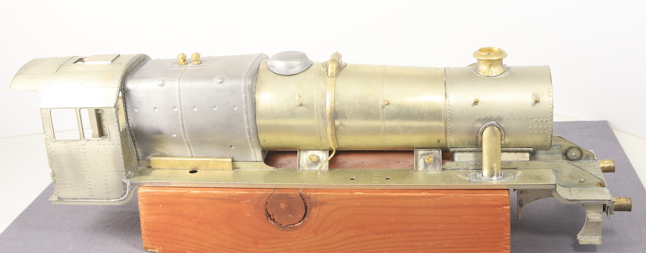
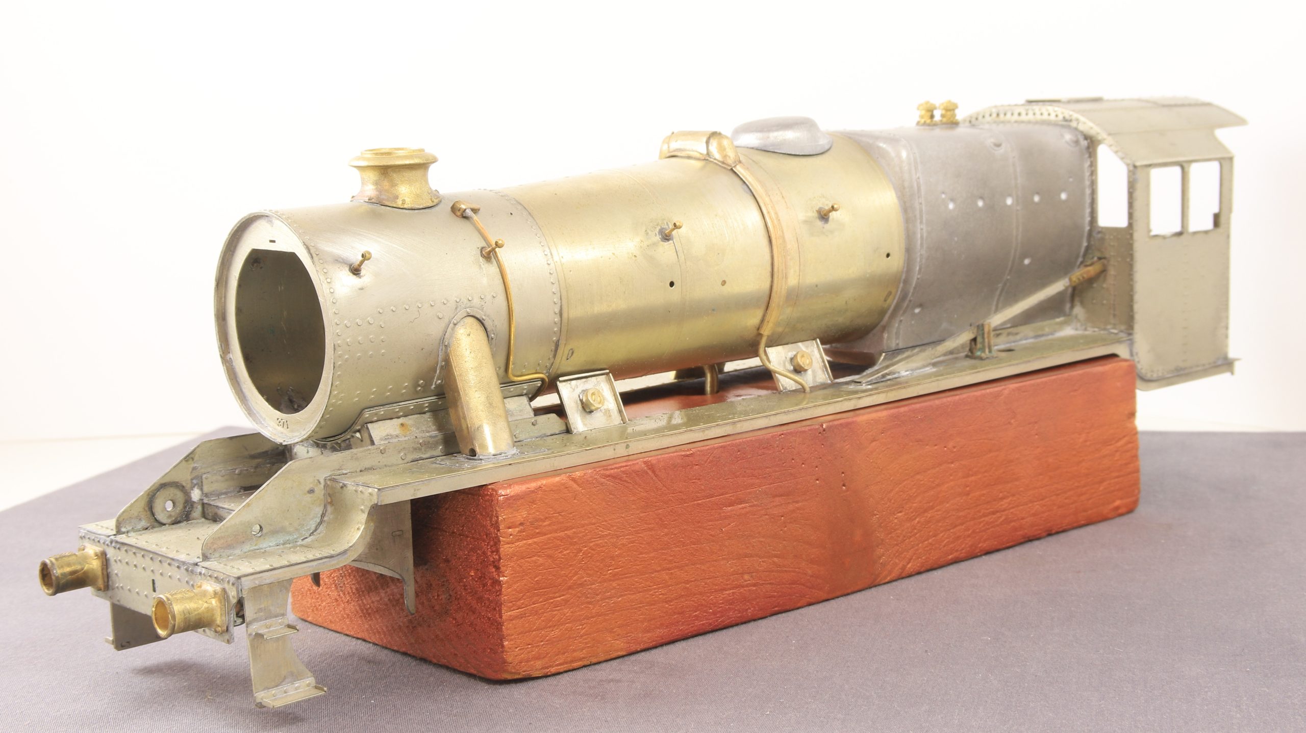
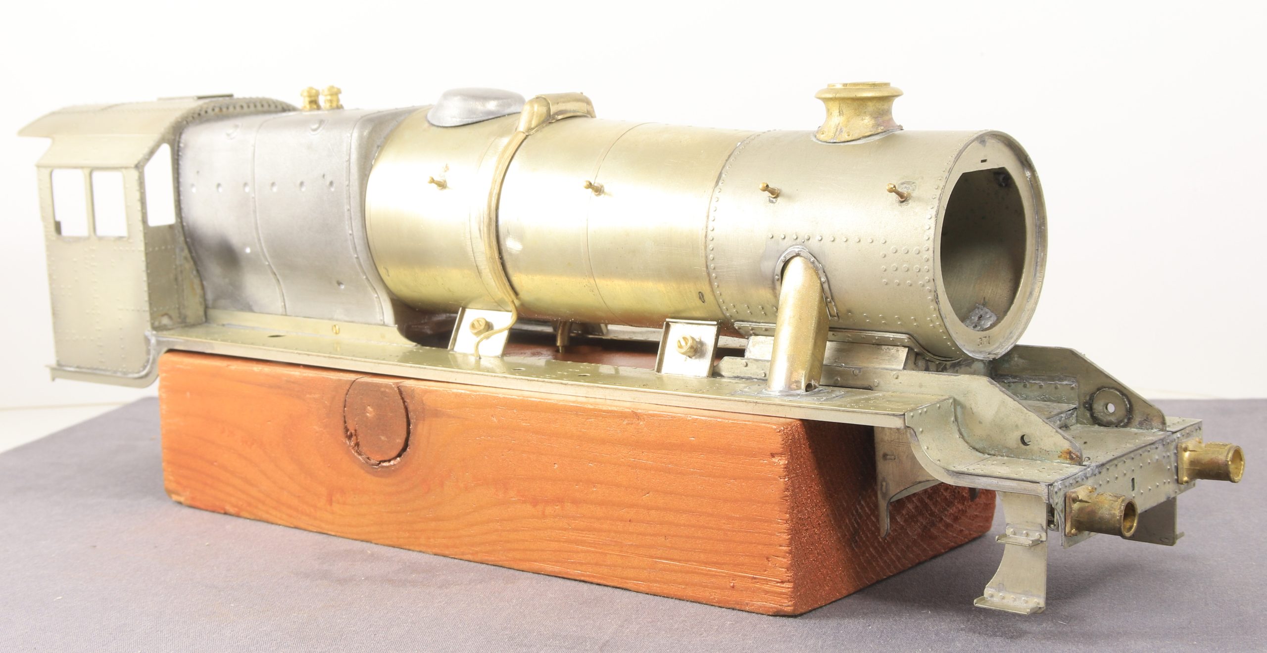
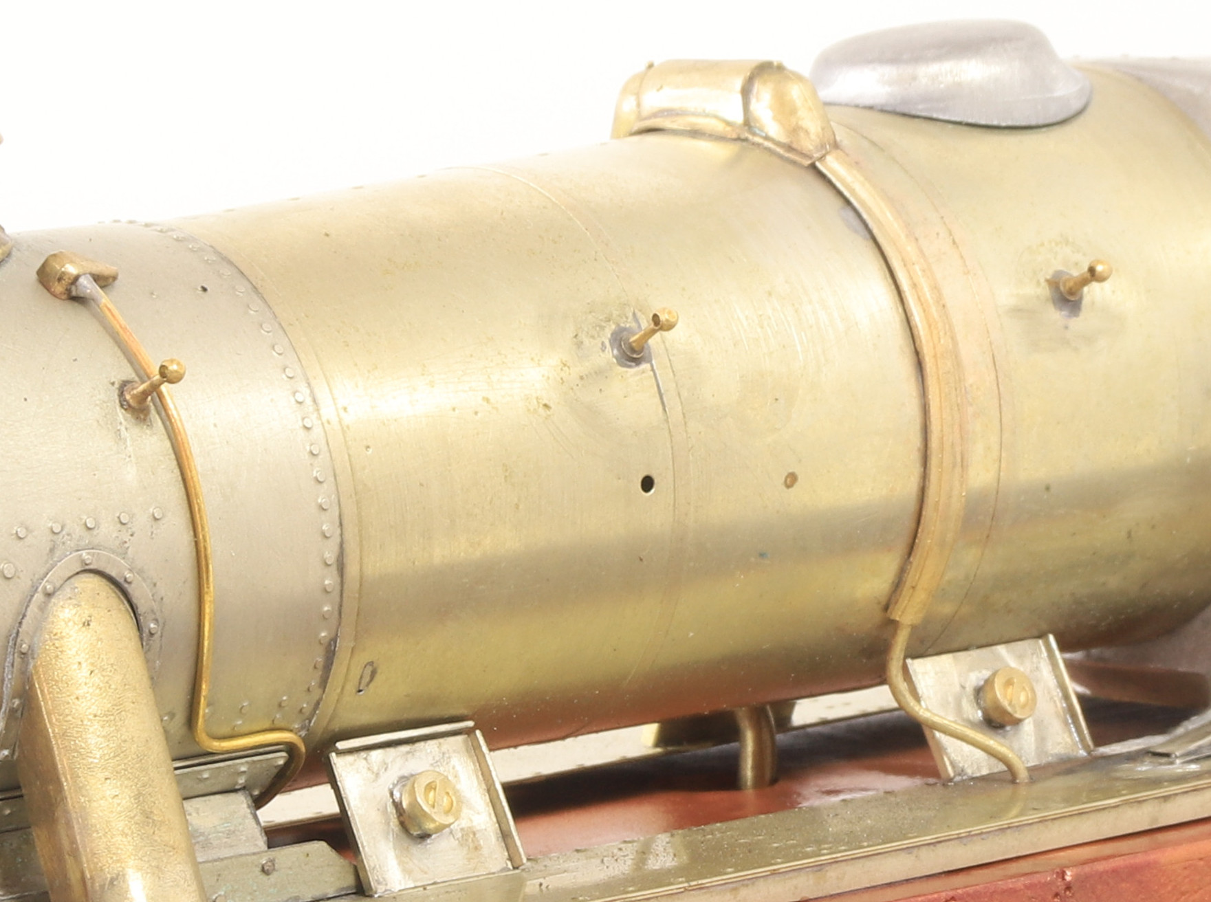
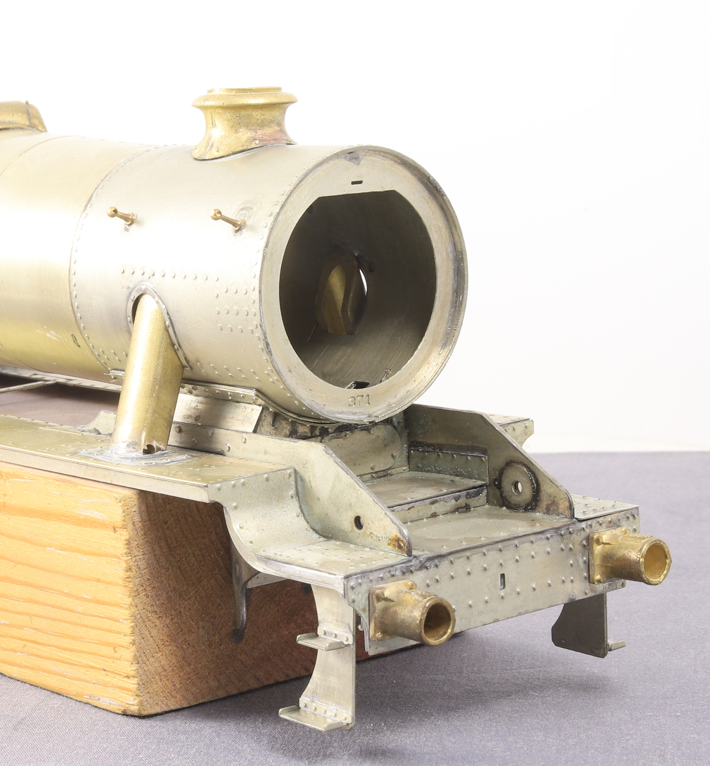
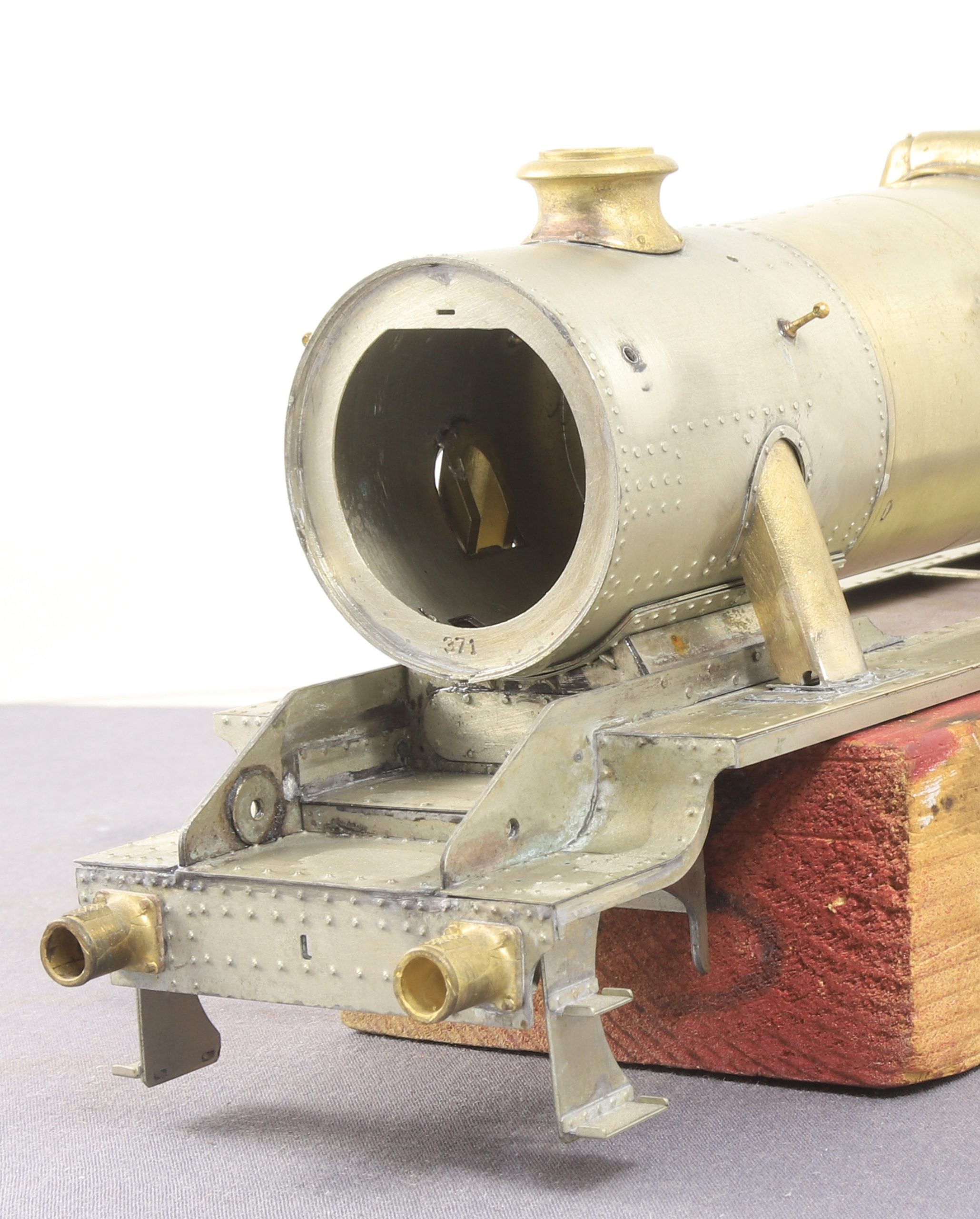
It was also kindly and discretely, pointed out that I had the dome on back to front. Which, was accompanied by a clear explanation of why it was thought to be so. As I read it, it made perfect sense and I could see clearly why it was on back to front. Life got in the way and I was unable to do anything in the workshop on Wednesday but I awoke early yesterday with my mind working on how I might safely remove the dome. I’d run elaborate scenarios of using the microflame while wrapping vulnerable bits in wet tissue ad using various items as heat sinks etc.
When I got into the workshop after breakfast I looked and realised that although I had fixed the boiler in place and removing it although not impossible would require undoing and refitting a number of parts. I could in fact get my low melt soldering iron into the base of the dome via the opening in the base of the firebox.
Then it was a relatively simple matter of starting to ease it off with my nails while heating the underside with the iron then once i had it move enough I used a pair of wooden coffee stirrers as pry bars to ease it off the rest of the way without damaging either the casting or the boiler. it was one of those situations where another couple of hands would have been helpful but I managed.
Oh what a few years of experience brings. Back when I started this build, if someone had told me then that I had the dome on the wrong way around. I would never have had the courage to remove and refit the dome and at that point the boiler was a separate entity.
As a small side note not long after the Finney7 team took over the range I bought a set of etched pipe clips (a side product from the Duchess kit) and this is the first time I’ve remembered to use them. Of course as soon as I touched the first one after thinking it was fixed in place, it pinged off, never to be seen again.
After a reply from a gent who knows much more about the real thing than I do, my life was made easier when he said that the smaller pipe didn’t actually feed into the down vacuum pipe put was clipped to the back of it. This saved another delicate 0.4mm drilling job.
It’s not exactly clipped but it’s out of sight behind the vacuum pipe when fitted so well hidden.
The observant amongst you will note, that the small pipe at the smokbox end was a casualty of my ministrations. So that will need reattaching.
Also, since the photos were taken I have shortened the union at the rear of the vacuum ejector which holds the pipe that goes into the cab. It’s now more ‘nut’ like… Plus I’ve cleaned up much of the excess solder even though it’s out of sight.
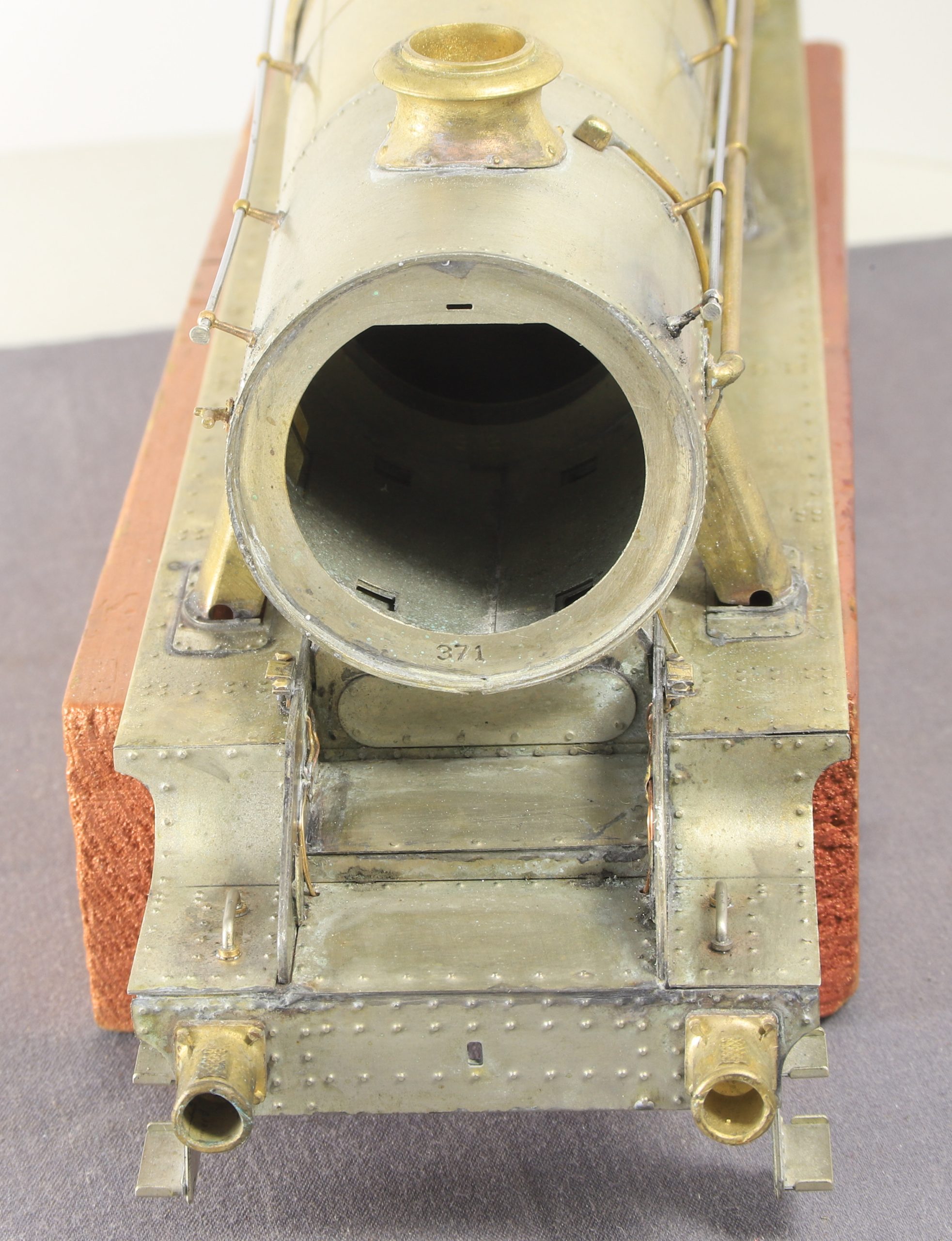
One of those jobs that I thought might take a bit of time and effort, actually went quite smoothly. Aside from a few minor adjustments and having to add a top piece to the two front backing plates because they were not included on the etch and there was quite a big gap above them which needed filling easily made from scrap etch, bent and then cut of with the guillotine.
Probably not the clearest in these photos but I also fitted the top feed pipes and the small casting and associated pipework to the smokebox.
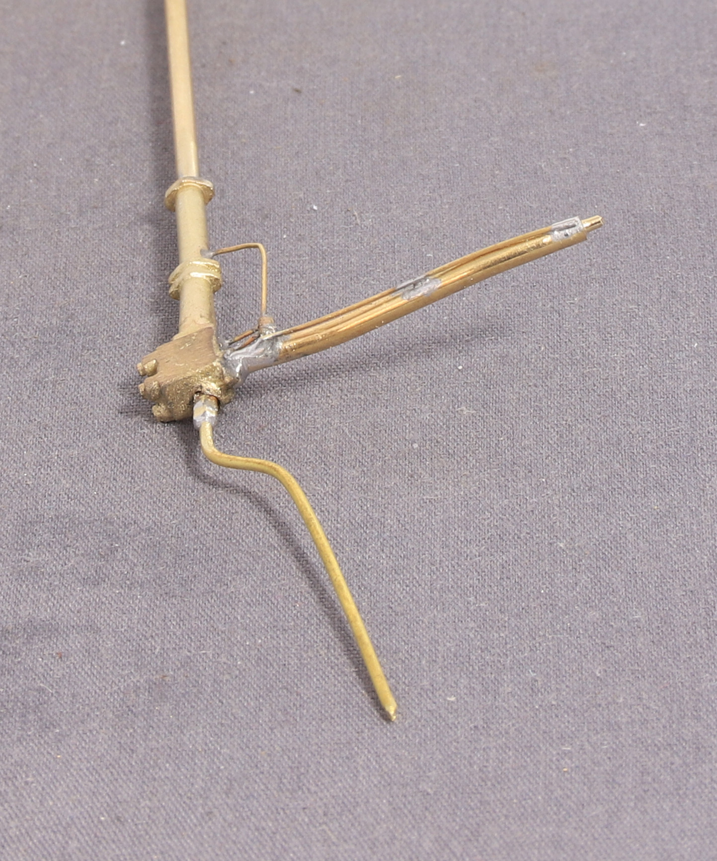
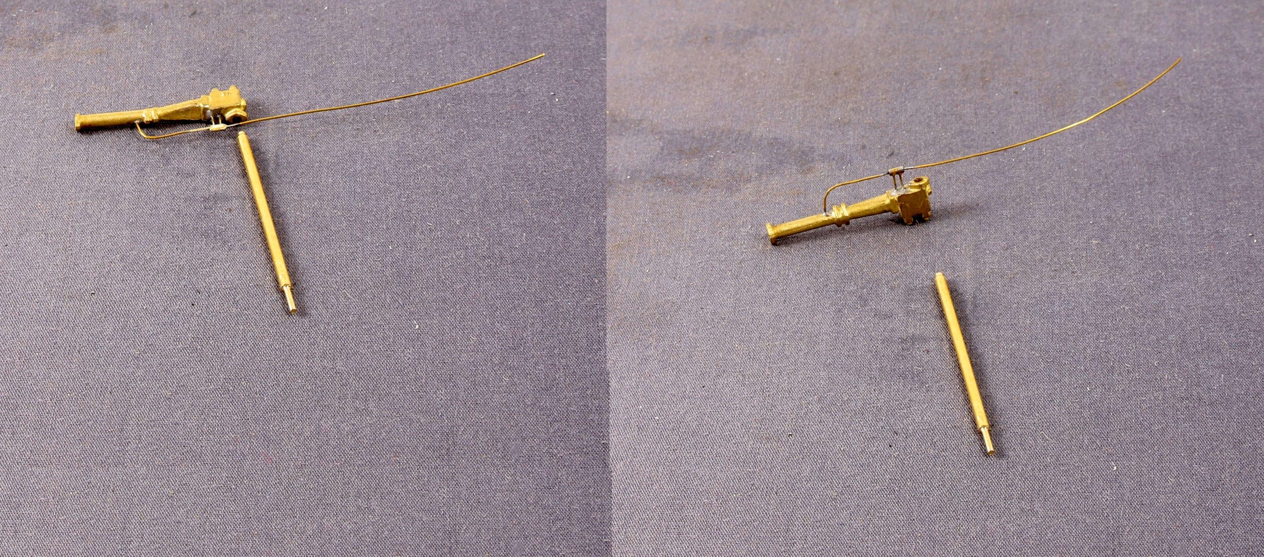
Having got the steam pipes in, I decided to work my way down one side at a time with the detailing. The vacuum ejector looked like it was going to be fun so yesterday I made start on that.
The elbow casting is provided in the kit but no provision is made for the small pipe and it’s connector nut that comes out of the bottom of the elbow. A 0.4mm hole was drilled and some 28 gauge brass beading wire soldered in. With a slice of tube filed to a hex to represent the nut.
Then came the pipe clamps. There isn’t any provision for this in the kit so I made some ‘split pins’ from 0.8mm half round brass wire and another slice of slightly thicker tube to create the flange.
Next is the ejector itself. The casting as you might expect comes devoid of pipework so more 0.4mm holes ensued pipes again made from 28 gauge beading wire and another length of microbore tube. This was cross drilled on one side to take the vertical pipes. I still need to drill the thicker down pipe to accept the horizontal pipe but first I need to make sure that it fits to the footplate and is bent in the right planes. There is also another pipe to fit to the rear of the ejector casting that goes into the cab.
In my last post I forgot to mention that I was having a great deal of trouble getting the steam pipes to sit and stay in the correct position for soldering. In the end after a bit of careful measurement I turned a small steel button.
This was to fit on my wooden cradle, under the base of the steam pipes and just protruding past the first layer of etch to allow the steam pipes to sit as desired. It certainly made the job much easier.
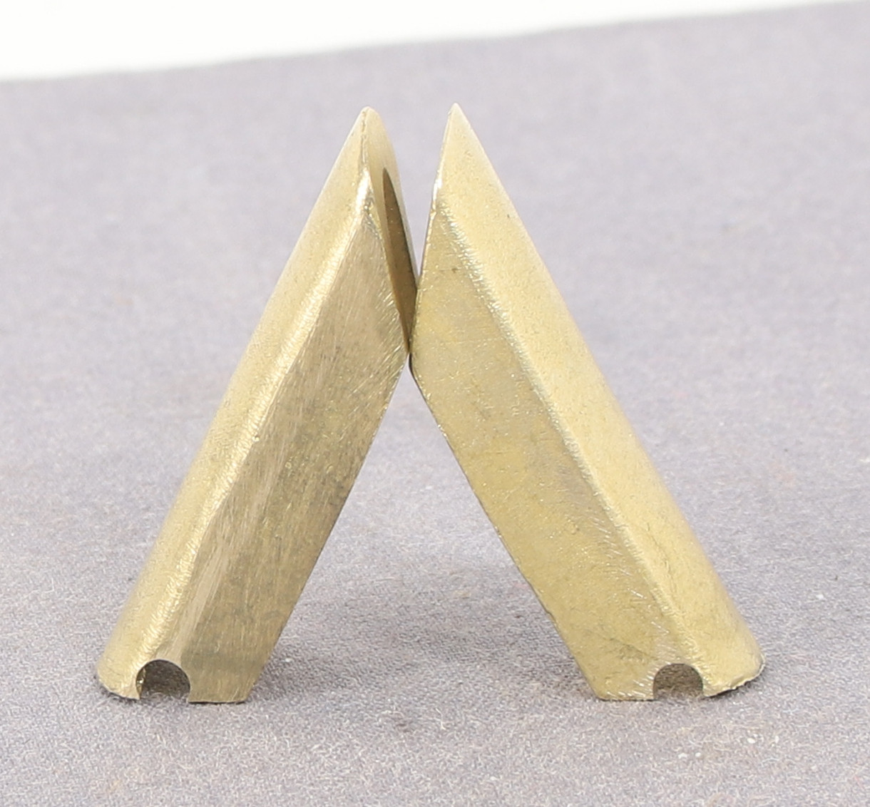
Having had a short break from loco building while finishing and painting the Bolster wagons and putting together the 3D cranes. Yesterday I fitted the horn guides and front frame spacer to the N10 and today I fitted the steam pipes and worked out where the holes for the sand box fillers need to to be made in the filler backing plates for the 8F.
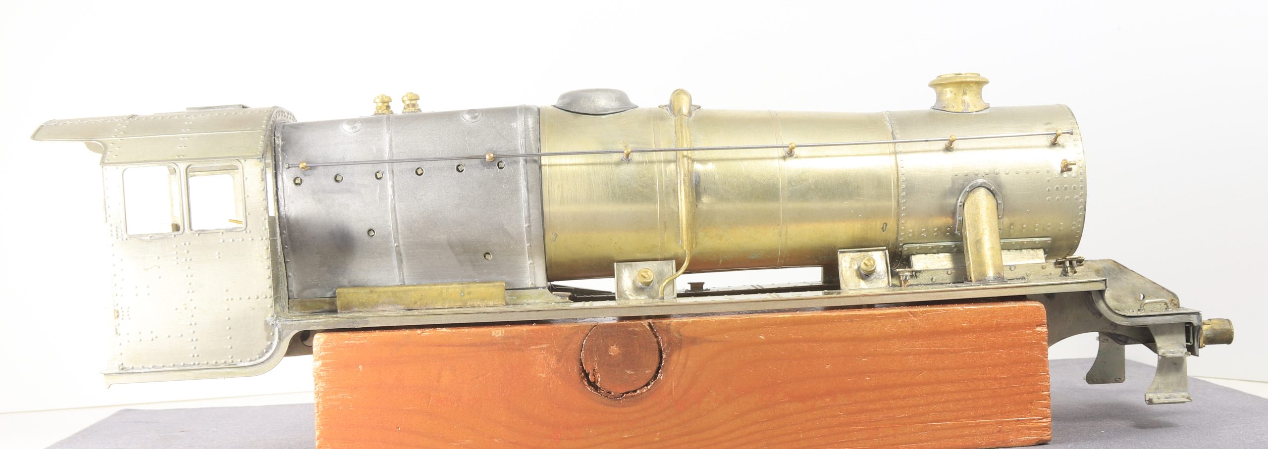
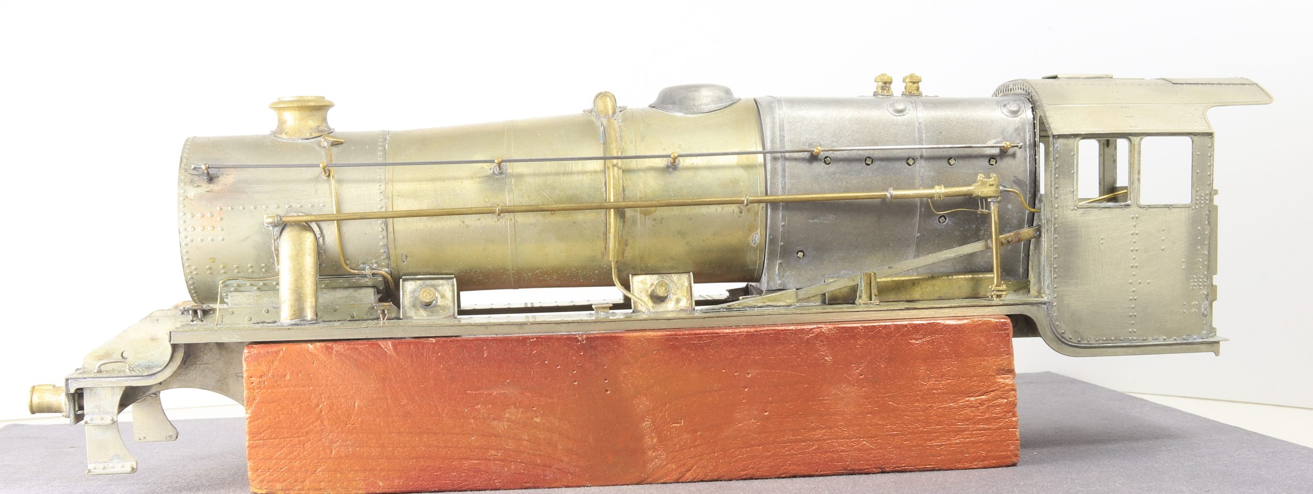
No photos of the N10 yet but I have some of the steam pipes on the 8F
Having spent eight days making the jig it only took about 20 minutes to actually do the job.
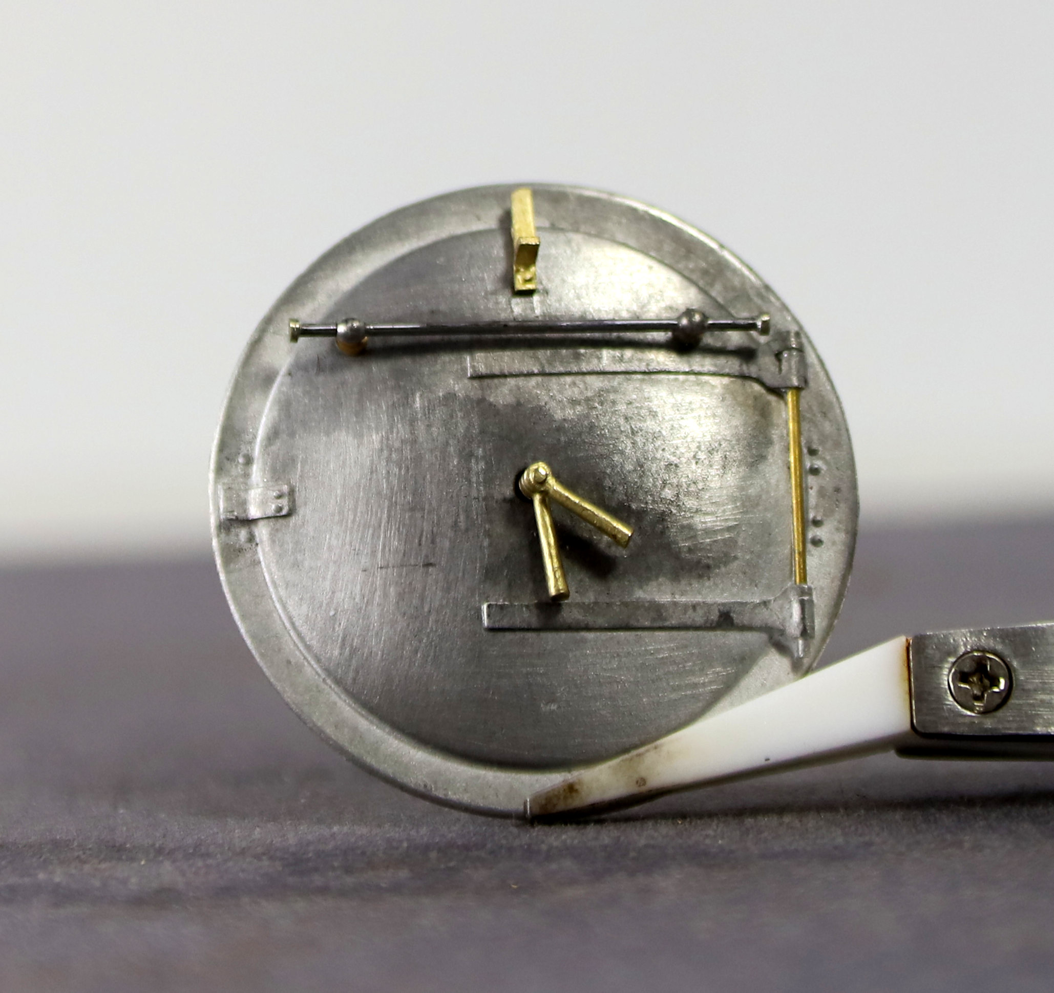
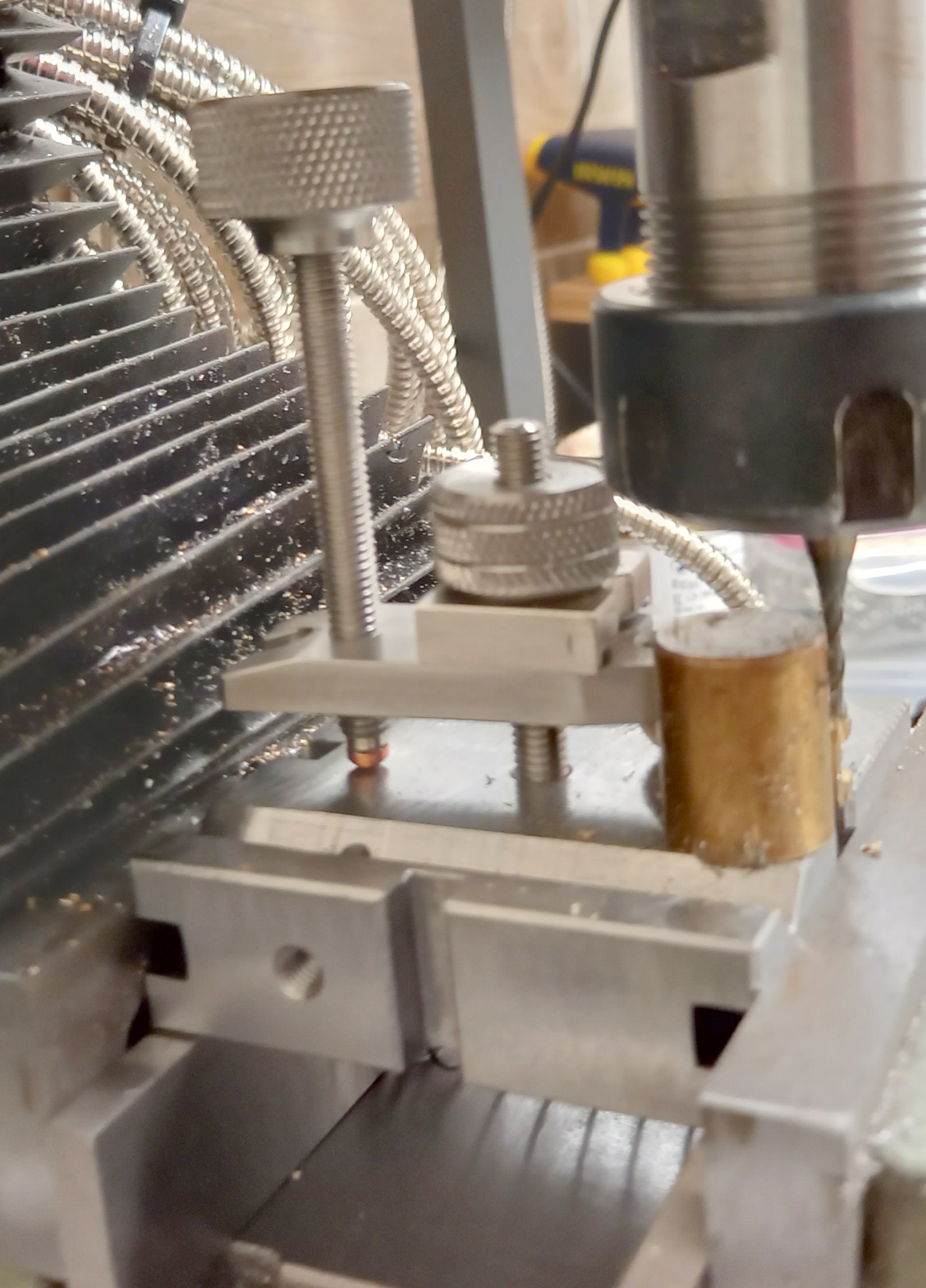
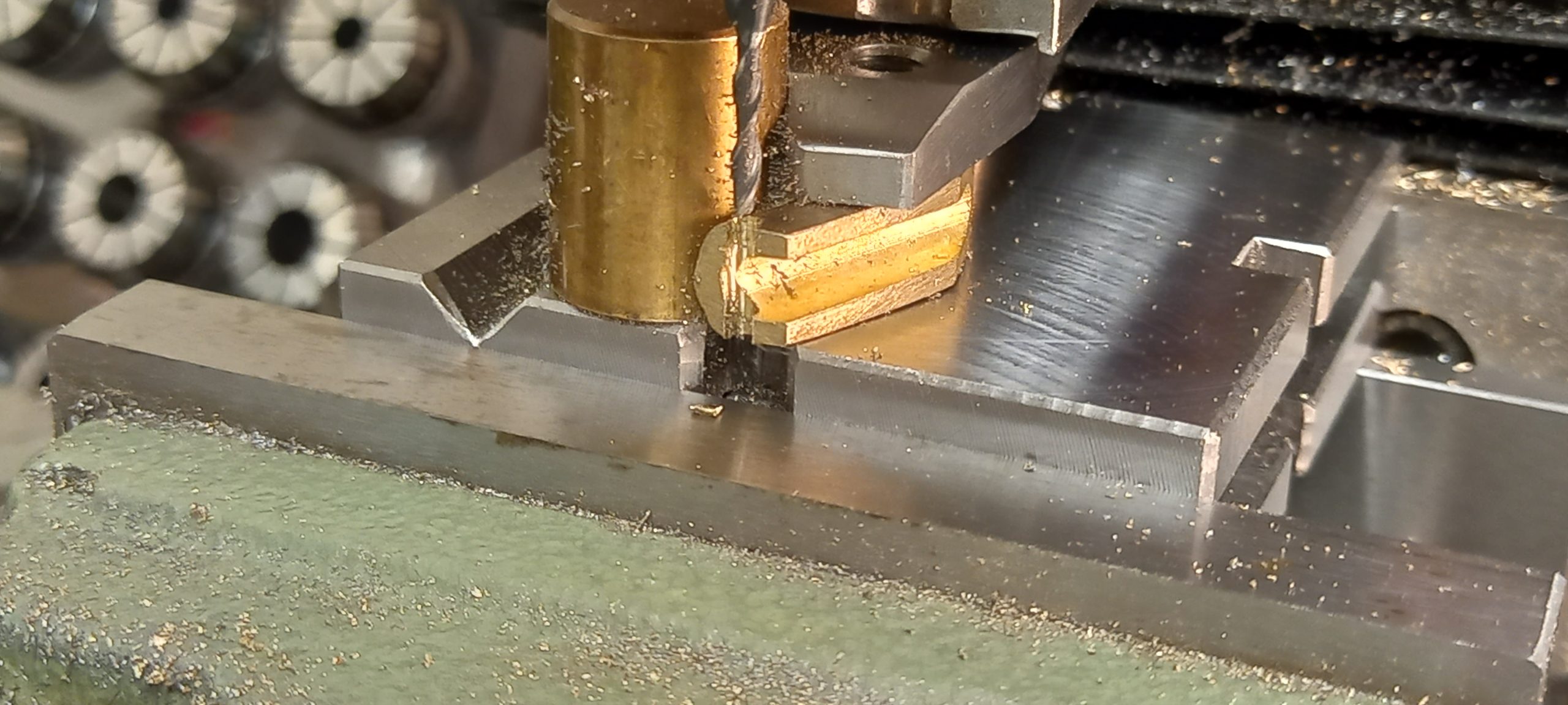
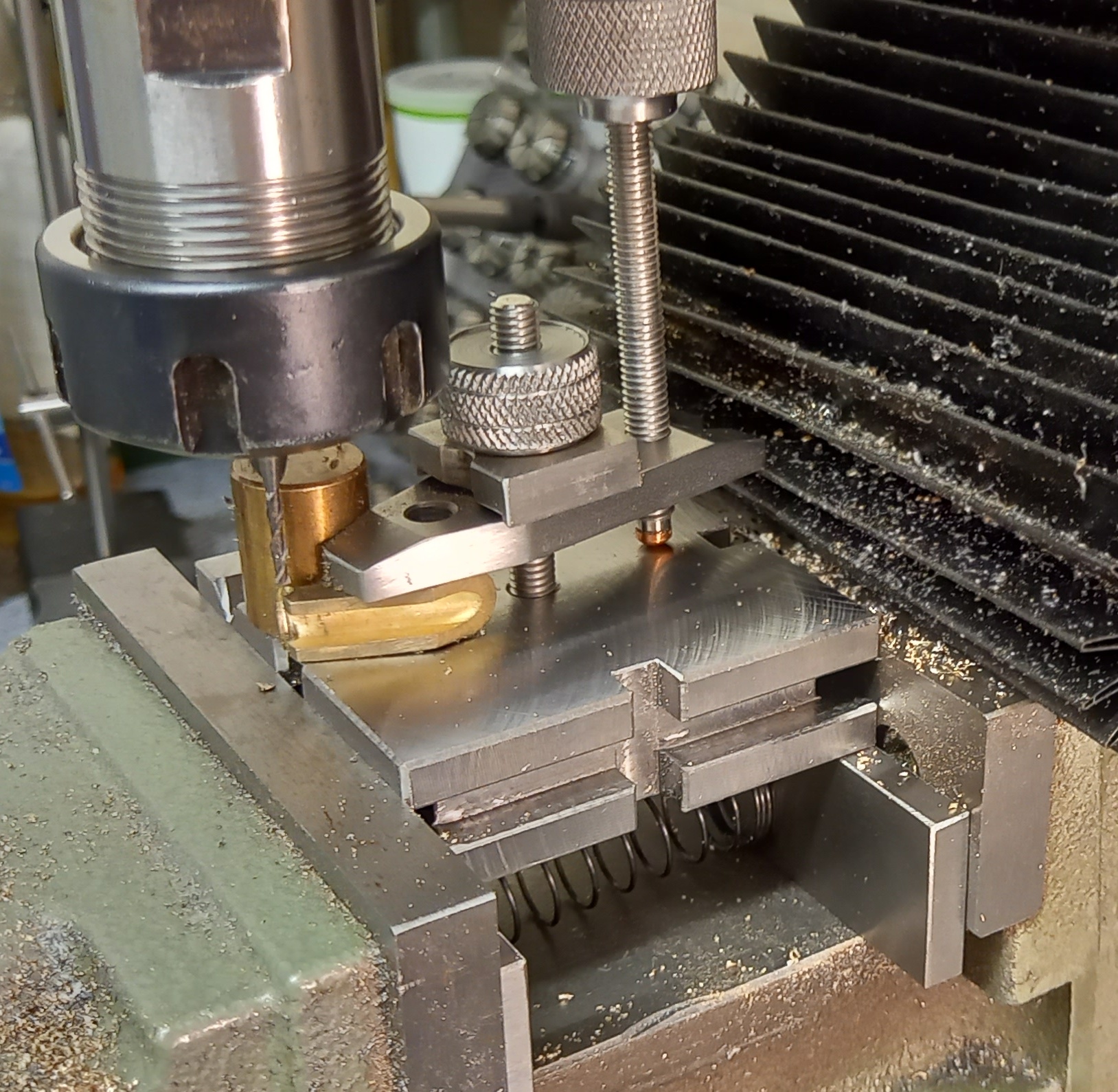
Yesterday morning, I decided to see if I could salvage the damaged original nut that I made for the finger plate. It’s a good job I did because the nut that I had made to replace the damaged one was too big to allow my 2mm milling cutter to get close enough to the job without catching on the nut. So I dug out the now smaller diameter original and that allowed enough clearance to get the job done.
The brass cylinder that you can see in the photos is actually a strong magnet inside a brass sleeve which came with my RSU but I have never used it before. In this instance it’s being used as a reference stop so that I can easily locate the second steam pipe in the same place for machining.
I used a parallel to align the bottom face of the casting with the edge of the finger plate so that I could mill/drill into the slot.
I am pleased to say that it did the job exactly as it said on the tin so to speak.
It also occurred to me this morning that having replaced the 1/4-40 tpi and 1/4 UNC threaded parts with M6 I can also use standard M6 hardware in the finger plate if I need even more clearance at any point in the future.
Well, I would be lying if I said that getting the chassis running with all the motion fitted was anything but a trial. Much of it my own doing. I am not sure how but I had scaled the drawing wrong so my many attempts were all destined to failure I just didn’t know it yet. It was mention of the scale size of one of the rods that Ian Allen @lancastrian) posted on the Guild forum that made me double check and find the error. A trial assembly of the final version of the return cranks confirmed that they were indeed almost a millimetre too long between centres.
I confess, that this almost did me in and I nearly consigned the 8F to its box for another decade. Saner heads prevailed and I recalled the drawing, redrew the return crank in Fusion 360 and created an updated working drawing. From there I made a ninth set of return cranks and again I made an error in so much as I predrilled the cranks and the small bosses that I added to clear the ends of the studs protruding above the face of the crank. When I then soldered them together, I hadn’t noticed that the holes were slightly out of line until I tapped them the tapped them and the tap went in at angle. So, I started again and this time I made four return cranks with the view that I could pick the best two.
This was taken part way through making them. – I did trim down the boss on the deeper pair after testing.
Having taken great care in the shape of them I also only drilled a pilot hole in the bosses. Then I clamped the cranks to my Metalsmith drilling plate in the mill vice and drilled right through to ensure that all the holes were aligned.
Next, I used a small engineers clamp to clamp the cranks to my tapping jig to ensure that the tap was aligned to the hole and then they were tapped 12 BA
I also used my homemade tap spinner to reduce the risk of breaking the tap.
Finally, I had two pairs of cranks fitted with miniature studs
A test fit had me heaving a sigh of relief as they fit and the motion turned over under power but there were a few clicks where the bits were catching. I knew that clearance was always going to be tight so I patiently worked my way through the various parts easing them.
They included but were not limited to, filing two etched bolt heads off of the insides of the expansion links; filing the bottom front corner of the new valve blocks to allow a minute amount of extra forward travel; turning the head of the 14ba steel screws that retain the combination lever to the valve block down to the thread thickness while retaining the slot, to allow them to be easily removed. Again, to allow a minute amount of further forward travel; easing the faces of the connecting rods to allow the expansion link to pass without catching. – Incidentally I measured the thickness kit provided connecting rods at 1.7mm and the Premier ones at 1.5mm so had I used the kit rods that problem would have been exacerbated.
I also replaced a couple of 14ba brass screws (which retain the expansion links) with some homemade nickel silver replacements with the view that they would be slightly more hardwearing than the brass ones. In fairness given how little mileage my locos actually do. this may have been overkill on my part.
After all that I had a smooth-running chassis. The tinging noise that you can hear is because I haven’t permanently fitted the retaining pins that hold the radius rod and the combination lever together yet so there is a bit of slop in them.
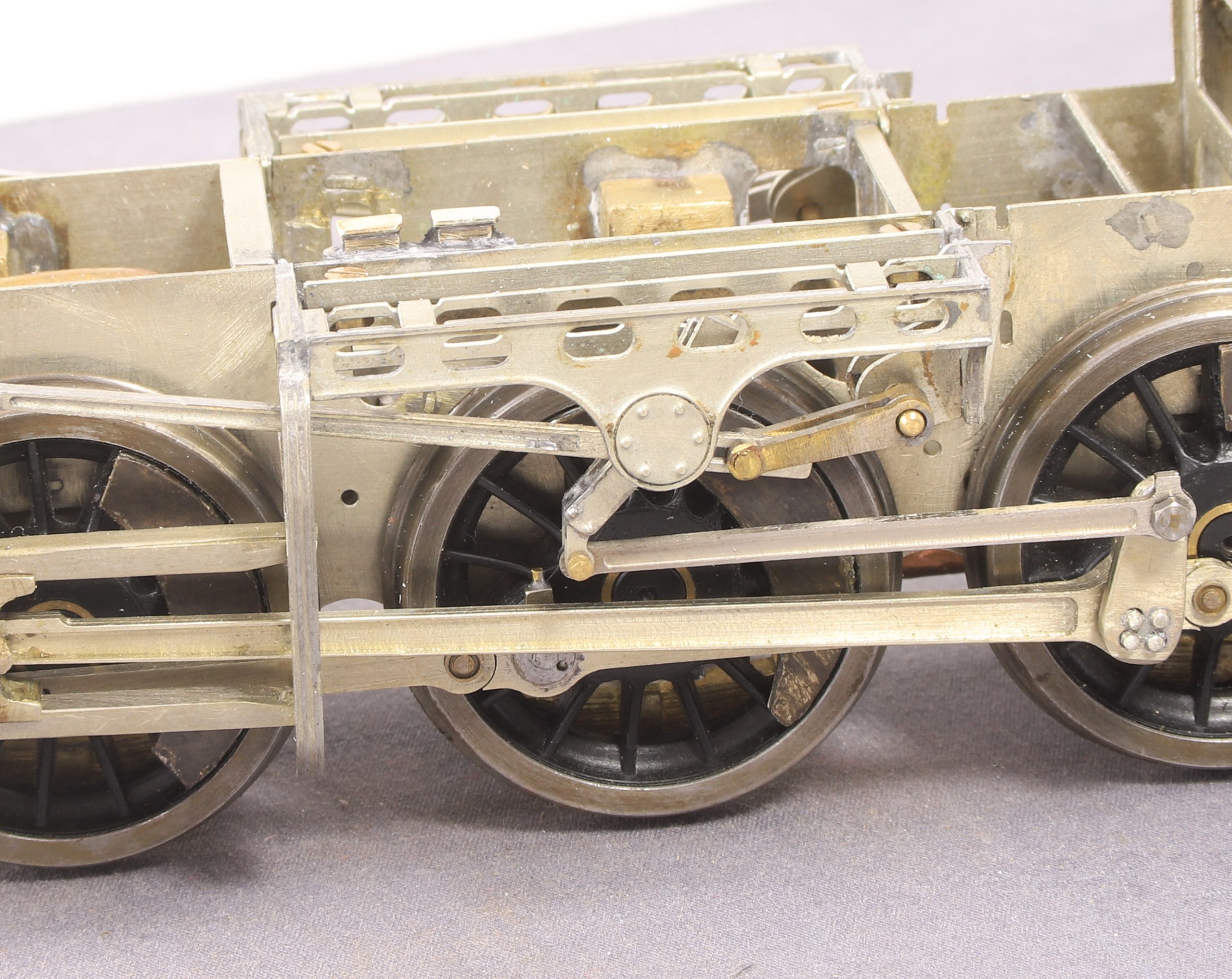
Well, that proved interesting. I removed the two offending driving wheel springs and I confess that I was surprised when that didn’t fix anything. The restricted movement still remained, so further investigation was required.
Looking a bit closer revealed that the problem was being caused by the compensation beam hitting part of the ashpan/gearbox housing arrangement.
Once I worked out the issue my first thought was how the devil do I get in there to cut out some material to allow more movement. I couldn’t see how I might get a piercing saw in and although I do have a shallow bladed razor saw, that was too deep to go in. The last resort saw wise, was to try a hacksaw blade. That too wouldn’t fit. Then I realised that if I unscrewed the motor retaining ring it might be possible to get a milling cutter in.
I gripped the chassis in the mill vice and with a 2mm two flute slot drill I carefully milled out a slot either side taking care just to go through the two layers of etch without hitting the compensation beam.
A friend has asked me to reiterate to anyone joining this thread more recently, that the MOK 8F kit that I am building was bought in 2010 and has been upgraded by MOK at least twice since then. Just in case anyone reading the thread is put off buying an MOK kit by reading my journey.
Additionally, when I started building it back in 2012, I didn’t have much experience (or confidence) in loco building. Hence mistakes were made by me and no fault of the kit through inexperience\lack of confidence. Which I now need to revisit having gained experience and confidence to rectify those mistakes in the meantime.
The latest of them being the realisation that the two rear compensation beams don’t move fully in one direction which leaves the second from the rear axle sitting lower than the others without any upward movement that should be allowed by the compensation beam.
Examination of the chassis has revealed that the issue is caused by my siting of the spring hangers for the second axle so I need to take them off and make adjustments to allow the full range of movement
It also doesn’t help that I had gone so far in building the kit as an LNER 06 but when I bought the whistle of Swindon Built 8F 8425 and decided to base my model on that example instead it required a few changes. Which are again, nothing to do with the quality of the kit as supplied.
When I mentioned them a couple of posts ago, I had also forgotten to post the retaining pins that I had made for the other joints.
I was a little concerned that I had the heads too thick but having looked at the GA and a number of photos, I have them about right.
These, were another little job that was quite satisfying and very therapeutic.
Stepping back slightly Ian Allen posted on the Guild forum that he’d had to add a small piece of brass angle to the rear of the valve guide casting to prevent the valve block from lifting. After making a note of it in my mind to watch out for, I was thinking about the potential problem while shaving this morning and I realised that I had probably solved the problem without realising there was a problem to be solved.
My retaining screw for the combination lever in the valve block is a 14ba steel screw which screws in from the back. The head of the screw protrudes into and slides, in the slot in the rear of the casting which I had enlarged previously.
After taking a few days off to do a video for the upcoming Gauge IO Guild Virtual show I returned to fitting the motion on the 8F. True to form it continues to entertain and frustrate in equal measures.
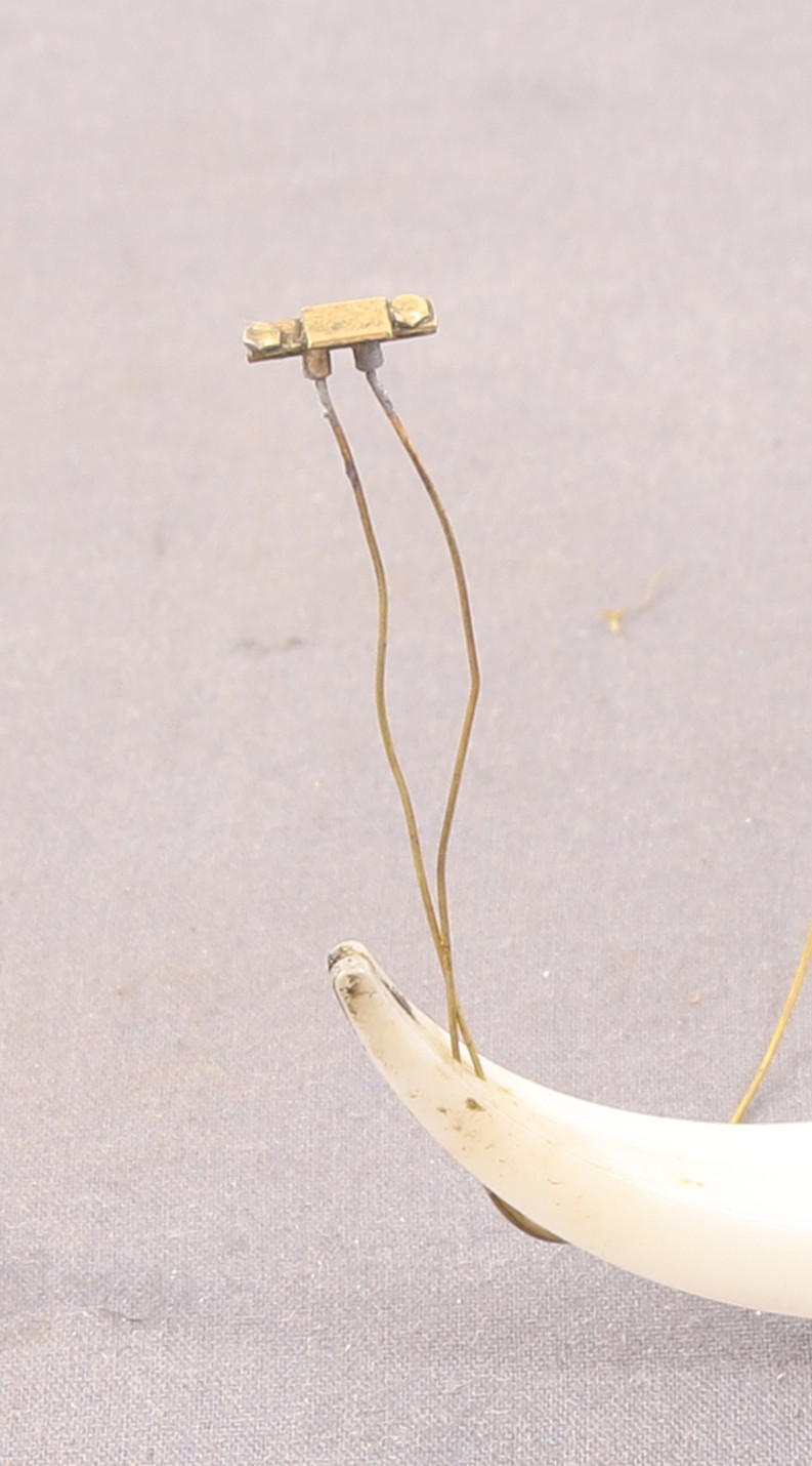
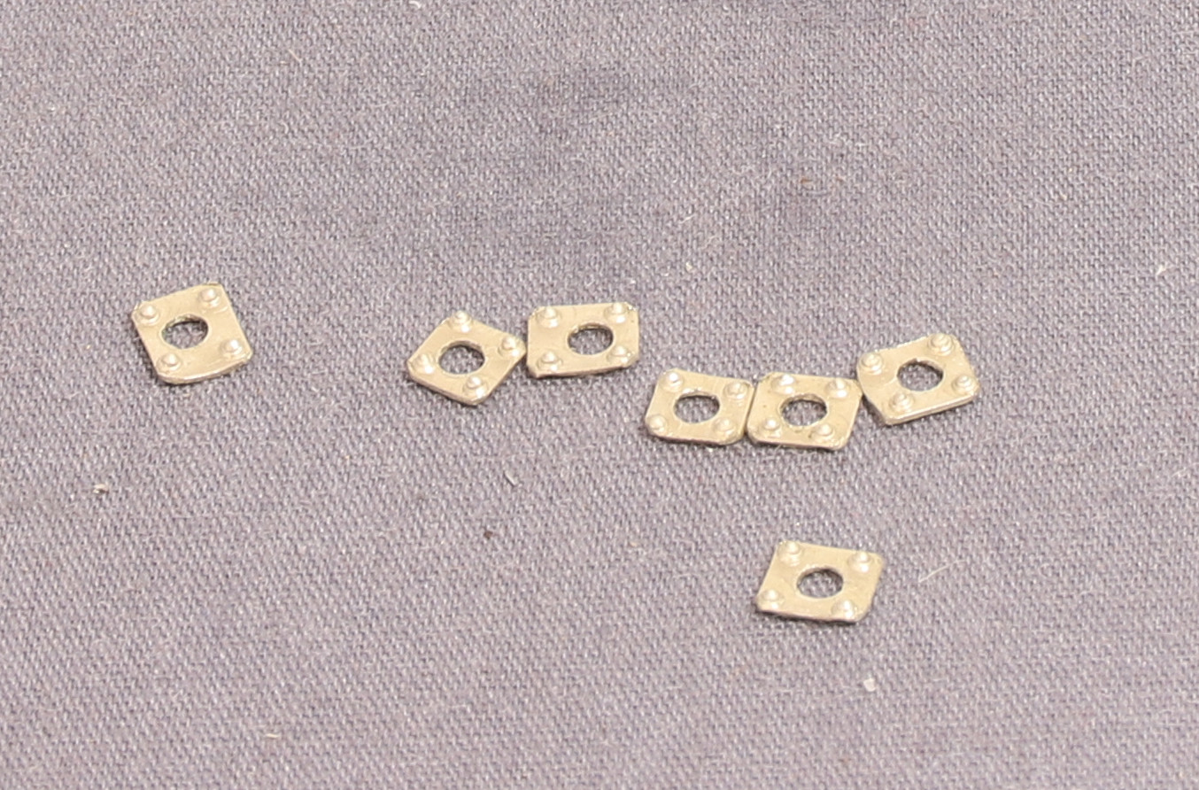
I started by fixing the links between the Drop Link, Union Link and Combination lever together with the pins and retaining washers that I made previously for the task.
It was once I had these assembled that I realised that once fitted in place the crosshead travel in the slide-bars was being limited by something and as it was it wouldn’t allow a full revolution of the wheel.
This was the limit of the forward travel. Initially I tried a bit of filing of the combination lever to see if that would allow it to move further forward.
This didn’t make any noticeable difference and I came to the conclusion that it was the fit of the combination lever in the “valve block” (? – I don’t actually know what this part is called)
This is what I came with the kit and I had drilled out the hole which was cast as a dimple on the centre line. I concluded that the hole for the retaining screw was too far forward causing the front of the combination lever to hit the lower front edge of the valve block causing the travel to stop at that point this conclusion was born out when I took it apart because one of the valve spindles had bent under the pressure.
I had also enlarged the side openings in the valve guide castings to allow better fore and after movement of the retaining screw.
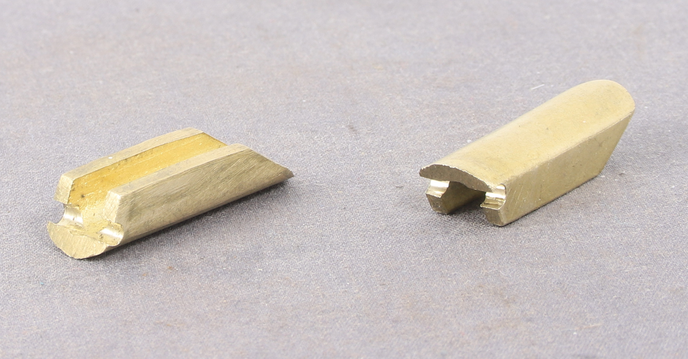
Having reached that conclusion I decided rather than try to drill out the existing valve blocks and potentially wreck them that I would make some replacements that were a little longer so that I could set the hole further back.
As is my usual practice these days, I measured the castings that I have I modelled it in 3D.
From there I created a working drawing
At this point I decided to make one to test the theory. If successful I would then document the second one.