You will of course note that this isn’t the same crane. It’s a second mobile (wagon mounted) version of the crane. I also managed to get a few decent renders


You will of course note that this isn’t the same crane. It’s a second mobile (wagon mounted) version of the crane. I also managed to get a few decent renders
Well, I finally managed to make the blessed thing move.
Or rather I made some of it move, for the life of me I cannot get the winch handle to rotate
I managed to add the handbrake albeit it took a number of tries before I got it jointed in the right place.
A couple of shots of the brake without the central support pillar to make it more visible.


Then with it in place.


It just needs some clevises for the stays and it’s complete.
After much more fiddling I arrived at this:


After these were taken I adjusted the angle of the job stay connectors

Then I realised that although I had fitted the inner geared roller which is for the brake I hadn’t done anything about the brake handle itself. So back to the drawing board…
Plus I still need to work out how to animate it.
Wow, it’s been a while since I last updated this topic. I confess that I have done very little 3D drawing since March mainly things that I intended to machine and modelled them to make working drawings.
I have done so little that when a friend whom I had drawn a number of items in the past asked me to draw up a GNR axle box and horn guide I had no idea how to go about it. Fast forward to a week ago and I decided that after drawing up the side control spring for the 8F that I needed more practice and to relearn how to draw in Fusion beyond the basics. Having recently messed about with gears and I had recreated some gears for my Medley Models Cravens Crane, I decided that I would attempt to draw up a hand crane similar to the one that I built some years ago from a Wagon and Carriage Works kit.
I wanted to go a step further than I have previously where I have built up a design as one entity and create components which would eventually create an assembly.
The W&C kit is designed to make either a wagon mounted mobile crane or a ground/plinth mounted yard crane. I have drawn up parts for both and started to assemble the Yard crane variant first as being the slightly simpler of the two.
It’s been a bit of a learning curve but an enjoyable one.


The last two NER vehicles that I have been finishing for a friend are brake vans and a bit of ingenuity was required to get the lettering in the small spaces between the frames and make the best of the available letters on the Fox sheets. You need lot’s of M’s and N’s for NER liveried Brake vans


Yesterday was spent lettering a few 3D printed wagons that I am painting for a friend.
NER K1 Cattle Wagon


NER P6 Hopper Wagon


A start was also made on a pair of NER V1/2 Brake vans but I struggled to fit the lettering in the available space between the framing. much dialogue ensued between us.

It was pointed out over on Western Thunder that the inset in the base should have the profile all the way around which I agree it should but I couldn’t work out how to do it. As always the minute that I started to reply to the gent who raised it I thought of how I might achieve it.

In conclusion, I got an annotated copy of the drawing so I was able to scale it to 7mm and do the complete pole.


Just after rendering the last few images I remember that this was supposed to represent something that had been cast so I went around and softened some of the edges using the Fillet tool.


Next I drew a couple of upright lines on the first sketch to determine the width of the base of the fluted section. Which was 8mm on my overscale drawing. Then I created another offset plane this time at the top of the column/base of the fluted section.

Then I created a sketch on that plane and drew a circle 8mm in diameter on the edge of that circle I drew another circle 0.6mm in diameter using these as a best guess for the size of the flute. I then used the circular pattern tool to create circle all around the inner circle. this ended up being 42.

Then on the first sketch I drew the profile of the flute.

I extruded this again symmetrically 0.3mm either way, to give me the 0.6mm thickness that I had determined (best guess!!!) was the flute size. Then I filleted the front edges to give me the round flute


Lastly I used the circular pattern tool again to create the circle of 42.


I even managed to get the render tool to work this morning last night I think that my machine was doing an update in the background and it was running like a dog.
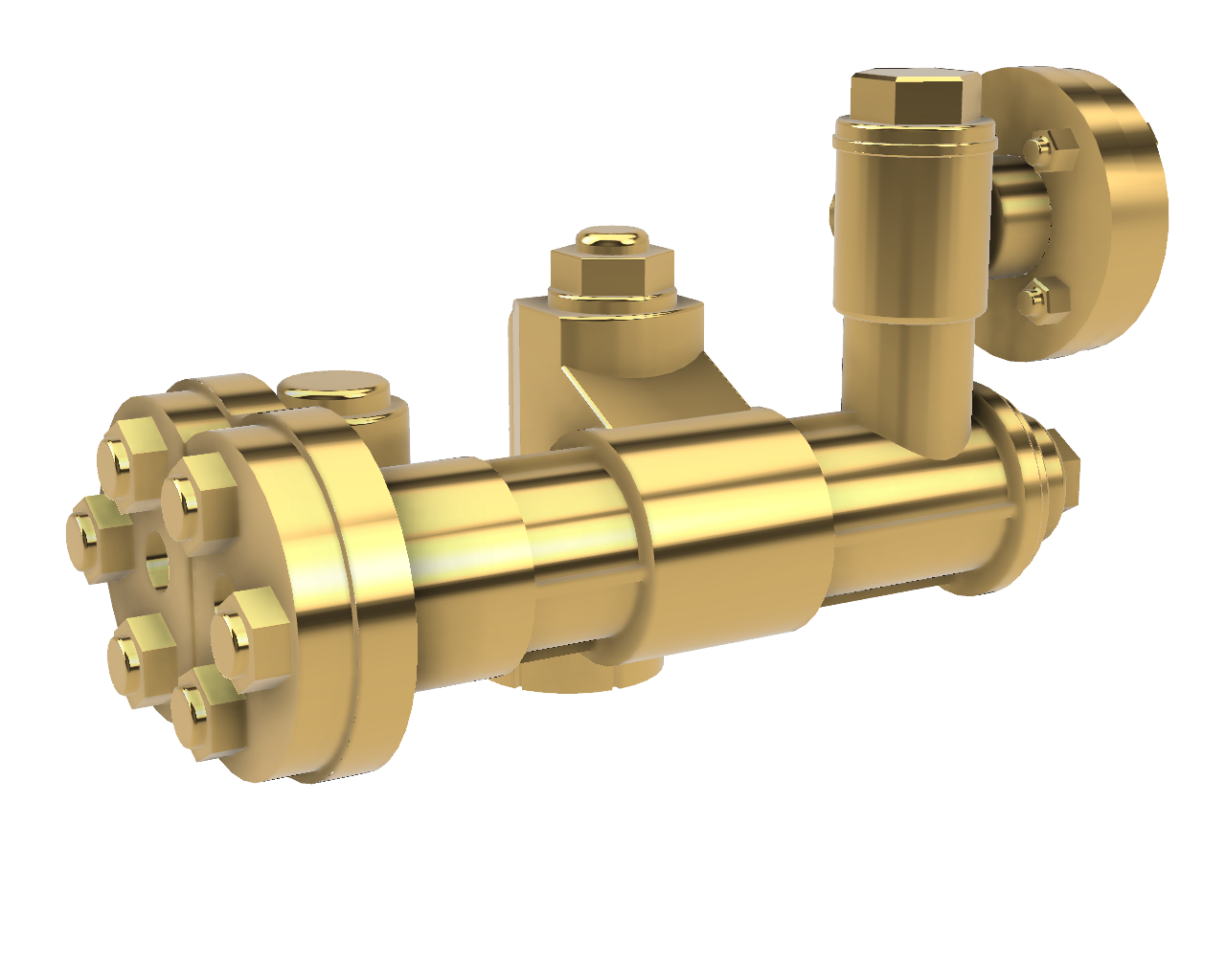
A friend kindly printed the Westinghouse pump and brought some along to Thirsk show yesterday.


I am most impressed with the print quality


I haven’t had much time for physical modelling this week so I have spend what time I have had doing a bit more drawing in Fusion.
These are an assortment of parts for the D2 test build when I get to it.


Front Sandbox, most of it will be hidden behind the front steps but some of it is visible.
Brake shoes, to take away the risk of shorts.


Finally for now, is the reverser for the cab


A friend who models in 4mm scale asked me if I would draw up some injectors for GNR tank engines (J52/53) so in between working on the lathe improvements while waiting for bits and pieces to arrive through the post I had a go.
He provided me with an annotated photo to work from which didn’t have every dimension on it so while I don’t think that it’s 100% accurate, it’s good enough for small scales.


Of course we need a handed pair which was the last job.

Those who read my ramblings may recall my mentioning and showing the build of a DJH LNER A3 that I built a few years ago.
I was never really happy with the paint job and Warren Haywood offered to strip and repaint it for me. I received it back from Warren and one of the casualties of the paint strip were the etched cinder guards from the cab side.
There used to be some really nice castings for Cinder Guards available from Hobby Horse but since Simon’s retirement and the business not being sold they are no longer available.
So I decided to have a go at drawing some up. My initial design taken from an A3 GA had the hinges with the two ears either side but looking closely at cab side photos of Flying Scotsman and Green Arrow showed me that they were different on LNER locos at least so I added the two hinges at the bottom of the image.
I plan to get these cast by Mike Hopkins and Chris suggested that I also do some assembled so that I can see what works best in terms of castings – all told I need 7 or 8 sets for various loco kits that I have in my stash.


I decided to do two options of the assembled item

Option one is with the guard in it’s open position at 90 degrees to the cab sideoption two is with them folded back against the cab side. To achieve this I needed to make them handed. I got the idea for having them folded back from fellow member Ian Beattie, who mentioned that he always models them folded back to minimise damage and I thought it a good idea.

I did screen shots for these as the renders were so bright you couldn’t really see anything….
I will share photos of the castings when I get them back from Mike.
After my recent adventures with horse drawn vehicles, I thought that I would have a go at drawing up a spoked wheel. The lack of availability of suitable wheels has been what has held me back in the past from doing more with horse drawn vehicles, which were so much a part of the railway scene in my chosen modelling era. Indeed my paternal grandfather was still delivering milk from his farm via horse and cart in the late 1950’s


The basic wheel and spokes took only a short time to draw up but it then took around an hour and a half to work out how to get the camber on the spokes. I deleted the ring of spokes multiple times before I got there.
No posts for weeks and then two posts in a day.
Although I have had these printed in resin by kind hearted fellow modellers, I also wanted to see what they would look like in Brass so I asked Mike Hopkins if he would add some to his next set of castings.


Well worth the money and the short wait.
After my efforts to create the lovely safety valve bonnet yesterday I was dismayed when I learned that I had orientated the ellipse at the top in the wrong direction. It should run in line with the boiler….
Today’s first task was sorting that out. All was not lost as I learned a bit more while correcting it and I have an even better end result for my efforts.


Next up I drew up a replacement chimney to the correct dimensions for the Class J and initially I added rivets around the base but Tom alerted me to the fact that the NER used countersunk bolts so nothing was visible on the chimney base after painting. A few steps back on the Fusion timeline removed them. It’s certainly much easier to remove them than to add them…
Although the Class J didn’t have a brass cap to the chimney the drawing that I worked from showed it so I couldn’t resist depicting it on the photos at least.


Finally I drew up a replacement dome so that should draw a line under this particular little project if you will pardon the pun.


After posting my earlier effort at the safety valve bonnet, fellow NERA member Tom Burnham pointed out that I had made an error and the the cover should be oval at the top not round. He kindly provided me with the info to put it right.


I am still being distracted by 3D drawing in Fusion. I have also discovered the render tool so the images look so much better.
As I have more than a passing interest in rolling stock I thought I would attempt an NER No2 Axle box.


A friend kindly pointed out that we mostly only model the part in front of the W Iron so I changed the drawing slightly

