A Dynamic Post……

Today has been spent making underframe details – namely vacuum cylinders and Dynamos.

First up is a Gladiator Dynamo. These are a bit plain albeit very nice castings as they come, so I added a block (from square brass bar) for the wiring loom and an eye to connect a restraining chain. The “wiring” will be cut shorter and soldered to the underframe once I fit it.

IMG_5605

Next is a bit of a comparison between the Gladiator dynamo and a Sidlelines example both are sold as LNER examples.

IMG_5606

The Sidlelines example comes with a bracket/adjuster so I made one up from scrap etch a piece of rod that I threaded and a 14ba nut to go with the Gladiator dynamo.

Last is one of a pair of Gladiator vacuum cylinders mounted on a set of Slaters V hangers from the spares box and some scratch built levers/pivots.

IMG_5604

The long soft brass wire will be bent round to meet up with the vacuum pipe that runs down below the solebar – when it’s fitted.

Gangway……S

One thing that I forgot to mention in the last post was the door ventilator bonnets. I bought some very nice cast brass examples from CPL but they had ridges along them. When I have studied the few photos that I have of these coaches the ventilator bonnets are smooth in appearance. Rather than spoil the CPL castings by filing them smooth I added them to the spares box and soldered a couple of strips off the edge of the etch together giving me a reasonable thickness that was the right width. Then with the piercing saw I cut enough lengths to fit all the doors that needed them and patiently filed them to shape. I think that the result was worth the effort.

yesterdays efforts were centred on the gangways, these are a set from CPL that are designed to cover scissor or suspended and have lots of spare parts to allow LNER gangways to be produced too if you have a decent photo to work from. I built them as scissor gangways as per the drawings and photos that I am working from.

The gangways as designed have a fold up concertina of black paper that fits inside the working scissor section. I need to come up with a different solution because I have made doors on the coach end that I want to be visible.

The photo below shows them in the closed and extended positions next to a ruler to give an idea of how far they move.

CPL Scissor Gangway closed and extended

I have included this shot to illustrate where I had to cut the top of the fold around inner support strip. The strip has tabs to locate in slots in the sides but the bit in between which curves over the top of the gangway is too long . Once I had worked this out I cut the strip in half and and worked in towards the centre at the top which is marked. I repeated this for the other half and then soldered them in once happy with the fit. There are some other strips that you press rivets out on to represent the Pullman style gangway that would also need the same treatment if used. It’s a simple fix once you realise what the problem is.

CPL Scissor Gangway

NBR D71 detailing the sides

This afternoon has seen me complete the detailing of the sides.

IMG_5597

The bump stops are the etched ones from CPL they are tiny and you need a fair degree of patience to use them. The best way that I found to fit them was to drill the hole 0.6mm solder in a piece of nickel (what I had to hand brass would do equally as well) rod and leave a blob of solder at the back with a short stub at the front. Run a broach through the hole in the etc to open it out and cut off and tidy up one of the bump stops etches. slide this over the stub of rod and push home with either nails or tweezers. Apply a drop of flux and use the microflame to heat the blob of solder from behind. The flux draws enough of the solder through to hold it without trying to get the iron to do it. I did manage with the iron on a couple but found it much cleaner with the microflame.

I received an MMP LMS Roadstone Wagon for Christmas so I count this as practice for fitting the many small details that come with it.

IMG_5600 IMG_5601

I managed to glean from photos the postion of the rather unusual handrail and the fact that the guards door had some visible hinges that I needed to add – these are not visible in many photos so they may be an LNER addition.

IMG_5599

Next up the ends and hopefully I will be able to think about soldering it together.

A little progress in the run up to Christmas

Progress has been steady and I have to confess to getting a little bogged down with the bogies. Not the best shot in the world but you can see where I had to hack out the ends of the bolster supports with the cutting disk.  This is what it looks like with the bolster assembled – nicely detailed.

IMG_5591 (800x533) IMG_5592 (800x533) IMG_5593 (800x533) IMG_5594 (800x533)

Once I realised I wasn’t making much progress with the bogies I decided to move onto the detailing of the NBR BG. I have a few more exterior photos now so I am just in the process of adding bump stops, grab handles etc. What I have done is make up some interior details, the first is the pressure gauge? (not really sure of it’s name) from some brass sprue, rod washers etc. The second is a very nice Sidelines brake standard casting which I have modified by creating a head mechanism that allows the handle to be side mounted instead of on the top. Once again scrap etch to the rescue – I based it on an outline drawing and the casting that Jim McGeown provides in his NBR Brake van kit.

IMG_5595 (670x800) IMG_5596 (537x800)

Still Bogie’ing along

Having got as far as fitting the bolster to the bogie frames last night I hit another minor snag with the Newbould bogies. The Kemilway bogies are designed that you can have one fixed with a little play and one that pivot’s from side to side. This is done via the three holes in the side of the bolster frames. The newbould bogies have the same holes so I attempted to duplicate the Kemilway set up and found that the fold down “wings” that have the three holes in the bogie frame are slightly too long and need a couple of mm taking of each side.

Newbould Fox Bogie Etch (800x548)

Now that I know on the rest that I have for other projects I will take it off while the bogies are still flat with a piercing saw – on the assembled bogies I had a to do it more crudely with the Dremel and a slitting disk. Thankfully it is tucked up out of the way and cannot be seen on the finished bogie.

A couple more making progress towards joining the fleet.

While doing the transfers on the L&Y van a couple of weeks ago I also put some on the Midland 8 Ton van. It just needs the coupling hooks blackened and weathering before joining the fleet.

IMG_5578 (800x513) IMG_5579 (800x533)

Chris also finished weathering the Midland brake van that has featured here a few times – this need the roof sticking down and the buffers blackening before it too joins the fleet.

IMG_5581 (800x533) IMG_5580 (800x533) IMG_5577 (800x533)

Whilst waiting for Peter’s reply I made a start on the bolsters. On both types of bogies there are quite a few parts to get to here.

First the Newbould:

IMG_5586 (800x576) IMG_5585 (800x742)

[img]http://i1181.photobucket.com/albums/x437/Robpulham/7mm%20Coaching%20Stock/IMG_55851024x950_zpsf6312cf1.jpg[/img]

Then the Kemilway – I haven’t got so far on these.

IMG_5587 (800x545) IMG_5588 (800x476)


Still being Foxey…..

The bogies trundle slowly forward, doing 4 at a time means a lot of repetitive tasks before appearing to get anywhere.

All the axles boxes have been soldered up and their face plates added etc. I test fit them in their respective bogies and then hit a snag.

These are the axle boxes – cruel close ups

IMG_5589 (705x564) IMG_5590 (714x565)

And these are the frames

IMG_5583 (800x533)

IMG_5584 (800x717)


The axle boxes for the Kemilway bogies slide right to the top of the horn guides but the Newbould ones hit the curved cut out for the bearing. Struggling to understand this I moved on with other things and emailed Peter Dobson. Peter replied and explained that this was an anomaly that was due to him using a similar design to his Gresley bogies where the bearing cut out is to accommodate compensation. Whereas these particular bogies are not design to be compensated.

His suggested solution is as follows.

IMG_5591 (714x565)

The suggestion is to cut of the area marked in red and either stick on or solder the axle box in place making them rigid. I am going to go further with the Kemilway bogies first to see if I can pick up any tips that might help to compensate these – albeit the Kemilway ones have a phosphor bronze spring plate for their compensation.

An amusing distraction

Back at the beginning of this thread there was a bit of banter on the guild forum around scale toilets for the toilet compartments. While talking to Peter Dawson I mentioned them, while they are not included in the kits he said that he had some that he could sent me and good to his word he did.

IMG_5548 (800x533) IMG_5549 (800x533)

They are not for the faint hearted to assemble (it took me two modelling sessions to get the toilet lid to stay in place) and I had to scratch build the bowl for the sink and find a tap in the spares box but good for a laugh.

More Foxey goings on.

Progress on the bogies hasn’t been quick due in part to me not feeling at my best and then due to the instructions on the Kemilway bogies telling you to drill through the shock absorber castings with a 0.6mm drill.
This hasn’t proved easy and 6 broken drill bits later, having only got through 4 of the 16 castings I abandoned that idea and took the safer route. This route had me drilling either end of the casting and fitting a stub of 0.6mm nickel rod in the bottom of the castings and then shortening the spring rod and inserting it into the top of the casting before solder them on.

IMG_5573 (800x471)

This is a shot with them complete on one of the bogies and very nice they look too – they have a nice chunky feel to them now
.
IMG_5576 (800x373)

I haven’t made much progress on the Newbould versions beyond soldering up the springs and studying the shock absorber castings which already have a screw thread at the bottom – this is what I believe the 0.6mm rod represents on the Kemilway version.

IMG_5571 (800x390) IMG_5574 (602x477)

Fox Bogies

Once the sides were on the D176 I turned my attention to the bogies – yes I know that I need the underframe but there is method in my madness honest!

I need some Fox bogies for the BG and I have in the stash several sets of Newbould model Fox bogies (they are desdtined for other things but can be borrowed in the interim…).

The things about the Newbould bogies is that nice as they are there are no instructions so I had the lightbulb moment of building a set of Kemilway and a set of Newbould in tandem so that I could cross reference parts to get an idea of how the Newbould ones go together.

Below are a couple of photos of where I got to. – All is done to this point without any soldering on either pair of bogies.

IMG_5563 (800x406)
First up the Kemilway version. They gave the first time that I have had to do any amount of filing, which was needed on the front and rear of the frames. To be fair the instructions do point out that you will need to make them fit properly.

IMG_5564 (800x402)
Then the Newbould version.

So far they are similar in many respects.


Kemilway D176

In tandem with the NBR BG I have also been progressing the Kemilway Diagram 176.

The duckets took a bit of forming but I got there in the end.

IMG_5560 (459x506) IMG_5555 (800x432) IMG_5556 (800x307)

The detail supplied for the guards compartment is really quite something.

IMG_5561 (595x531)


NBR D71 BG Revised Underframe layout

Following on from my last update Bill Bedford posted on the LNER forum that I had got the battery boxes in the wrong place and that the NBR didn’t use threads/nuts on their queen posts – apparently the bottoms of the queen posts are curved and the rod is continuous from turnbuckle to turnbuckle sitting in the curve. The reason that the battery boxes were in the wrong place is that the split box is split to allow a support rod to pass between them across the width of the coach from one queen post to the other.

So I sat it for a couple of days doing other bits and pieces – trying to make my own turnbuckles. Which turned out to be a dismal failure. I made a jig to bend the rod to shape and cutting short lengths of tube was no problem but soldering them together was a complete no no. I made a couple of jigs and even tried using the microflame and tiny bits of solder. Despite blackening the jig all I got for my pain and 4 hours of trying was it all soldered to the jig or stuck to the soldering iron as I tried to go in and out very swiftly.

So back to plan A where I buy them.

After wasting most of yesterday with the turnbuckles I did manage to get the battery rearranged and the queen posts modified to this stage.

IMG_5551 (800x533) IMG_5552 (800x533) IMG_5553 (800x533) IMG_5554 (800x533)

Starting to add the detail to the underframe

Moving slowly forward with this one although I am almost at the point where I can’t go any further until I get some more detailed photos which I have hopefully on the way.

Both upper step boards are now on and soldered in place and the battery boxes are all in place.

IMG_5541 (800x580) IMG_5540 (800x533) IMG_5539 (800x533) IMG_5538 (800x357)

I also soldered some pieces of scrap etch into the holes left by the V hangers/battery box ends etc – a pet hate of mine is holes in the floor especially when the vehicle has windows….

The queen posts as provided are half etched at the ends of the posts and are a little two dimensional – albeit they would be very easy to solder a length of rod to for the truss rods. I decided to do it the hard way. The reason for this is that the Kemilway truss rods are flat etches and I want something a bit more 3D so I thought that I would experiment on options on this one.
IMG_5542 (800x494) IMG_5543 (800x476)

First I threaded some short lengths of 0.9mm rod 14ba and then soldered them to the back of the queen post etches. I then got some Markits 4mm scale crank pin washers and filed a V slot in opposite sides and file a corresponding V on the ends of some 1mm rod. I had to make a template on some scrap paper to get the lengths right. The first one needed a bit of tweaking but the second was right first go.

You will also notice that I had to beef up the tabs on the queen post etch to fill the holes in the floorpan…….


NBR D71 BG – problem solving

The problem solving juices were flowing nicely last night!

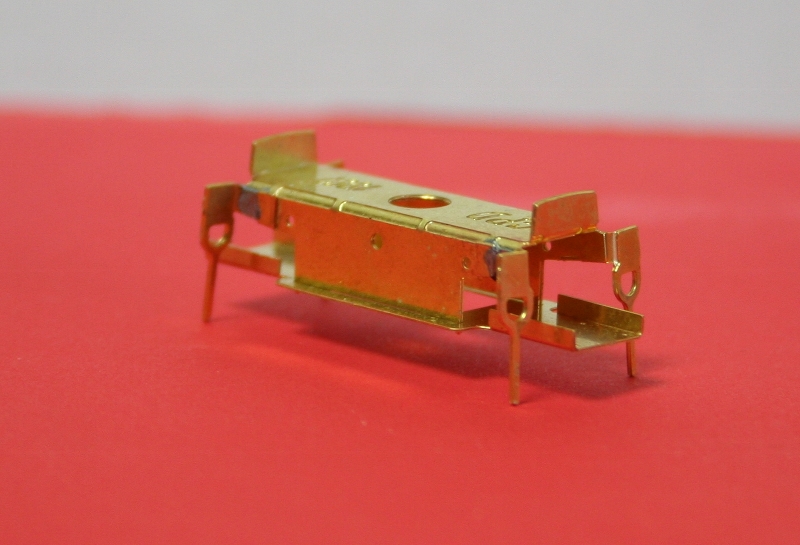
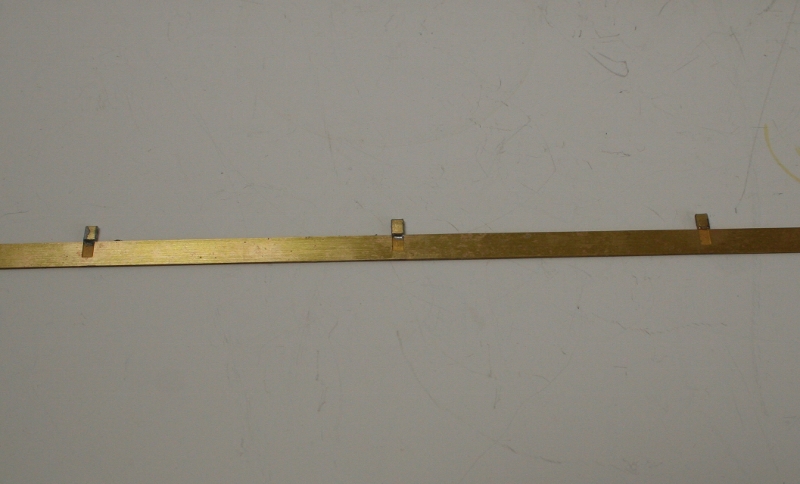
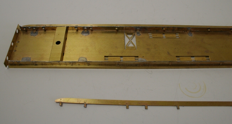
I have sorted a way to fasten on the upper step boards by folding strips of scrap etch around the half etched tabs (bearing in mind the size of the etched holes these would have been much better if they were full thickness not half etched – I cannot fathom the thinking behind having something that essentially provides support, half etched) and leaving a longer bit underneath as extra support (on all except the three centre ones where the supports for the lower step boards will go).

Hopefully the photos below will illustrate this better than I can describe it.

IMG_5532 (800x484) IMG_5531 (800x573) IMG_5530 (800x678) IMG_5529 (800x428) IMG_5528 (800x533) IMG_5527 (800x339)

At the moment the one side that I fitted last night is just a press fit and to be honest I could probably get away without soldering it, it’s that good a fit.

IMG_5534 (800x695)

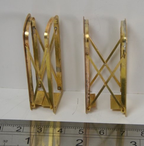
Above are the coach ends as supplied and I was thinking about scratch building some gangway doors when I had a bit of a light bulb moment. In some of the Kemilway kits there are two or three outer ends representing various changes over the life of the vehicle. So I cut a couple of these down to fit.

I plan to get some scissor gangways from CPL (they are GWR but hopefully can adapt them into something that looks NBRish…) so I wont solder these in until I know what I don’t need to do to fit them with the support pieces that are currently inside the openings.


IMG_5535 (800x777) IMG_5536 (723x800)
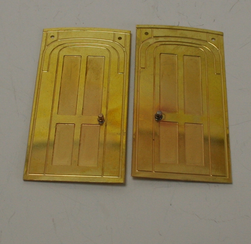
Readers of the whole thread will recall that on the Kemilway’s there are some really nice cast door knobs. I didn’t have any spare and although I am sure that Peter Dawson would sell me some if I asked, I decided to see if I could make some. I got a couple of short handrail knobs fitted a piece of brass wire through to fill the hole and then soldered it in. I then filed it until it was round again and then filed the top flat and it looks pretty good, bearing in mind how small they actually are!

IMG_5537 (560x411)


NBR D71 part 2

I am still sidelined by the NBR BG. :0)

One of the three battery boxes provided is actually split into two smaller boxes and as such does have any ends supplied. I made some from scrap etch to fill the gap basing them on the out ends which are provided.

IMG_5526 (800x602) IMG_5525 (800x601)


IMG_5518 (800x603)IMG_5519 (800x534) IMG_5520 (800x641)

next up is a shot of the guard’s ducket which is included but which needs the ends to be rolled very tightly in order to get it to fit nicely – the ends have half etched lines on the back to assist with this.

IMG_5523 (800x600)

And the rear view – so far I haven’t soldered it, it’s held by the tabs.

IMG_5524 (800x600)

And finally the door handle and hinge detail. I had some nice cast T handles in stock but the longer guards lever handles I made from 0.8mm wire annealed and flattened in a pair of smooth jawed pliers. because as I mentioned earlier all the etched holes are a bit on the big side I had to make and escutcheon plate to cover the hole and for the hinges I used folded scrap etc pinched together in the pliers to fill the hole and give a nice hinge representation.

IMG_5521 (800x600)IMG_5522 (800x600)


North British Railway D71 Bogie Brake Coach

A recent Ebay buy was a Bill Bedford kit for a NBR/LNER D71 BG, I say “kit” but it’s more sides ends and underframe. One evening I needed a bit of a distraction from rolling the tumblehome for the second Kemilway so I thuoght I would see how well the BB kit went together.

The sides are in two halves that are lap jointed a bit like Comet 4mm LNER coach sides if anyone has ever made them. I have to say that they go together very positively and were a joy to solder up. The sides themselves are nicely etched but the one thing that all the parts suffer from is that where there are holes for slots/tabs or door handles etch they are all etched too big.

In order to support the solebars I made up some brackets shaped like this

Brace

IMG_5510 (533x800) IMG_5509 (533x800)

There are some etched battery boxes included but the details was a bit 2D so I made up some hinge detail from scrap etch and 0.5mm wire.

IMG_5499 (800x534) IMG_5498 (800x534)

Next up I created the tumblehome. back up the thread I offered to detail how I do this so I took the opportunity to take step by step photos while doing it.

First stick a strip of 2″ masking tape to just below the windows.

IMG_5500 (800x401)

Place your piece of rod on the remaining strip of masking tape and roll it around until it’s stuck to the rod and up against the bottom of your side.

IMG_5502 (800x446) IMG_5503 (800x352)

Then continue to roll gently but firmly and the tape pulls the side into a curve.

IMG_5506 (800x533)


IMG_5504 (533x800) IMG_5508 (533x800)


And there you have it.

Regards Rob