This last weekend saw a little more progress on the Kirk coaches.
The seating is assembled for the all third and the roof made ready to fit.
Conversations on a few forums around how to attach the roof, have had the side effect of making me think about fitting passengers (which neither Don or I had considered/discussed). Due to me having already glued the floor in ( I won’t do that on future builds) I was exploring unobtrusive ways that I might make the room removable.
Having consulted Don who agreed that we should make provision for the fitting of passengers. – Albeit not that many due to the decline of passengers using the line in Don’s modelled period. I was still mulling over various ways of fixing the roof when I realised that the roof ends don’t quite match the profile of the ends of the coach. This is due to the way that Ian makes them by vacuum forming. When I say don’t quite fit I am sure that the discrepancy will be taken up by gluing the roofs on as originally planned. But if I attempted to screw them on in any way, I would be left with an unsightly gap at either end.
A bit more head scratching and looking at the way that windows fit I decided that I could make it so that the windows cannot be dislodged by handling (which was another fear of gluing the roof on) and that if I fitted some passengers before gluing the roof down, it would mean that Don didn’t need to gain access to do it later.
I had some Slaters seated passengers to hand and they provided a welcome distraction and rekindling of interest,which I have to confess due to pressures at work was waning a little.

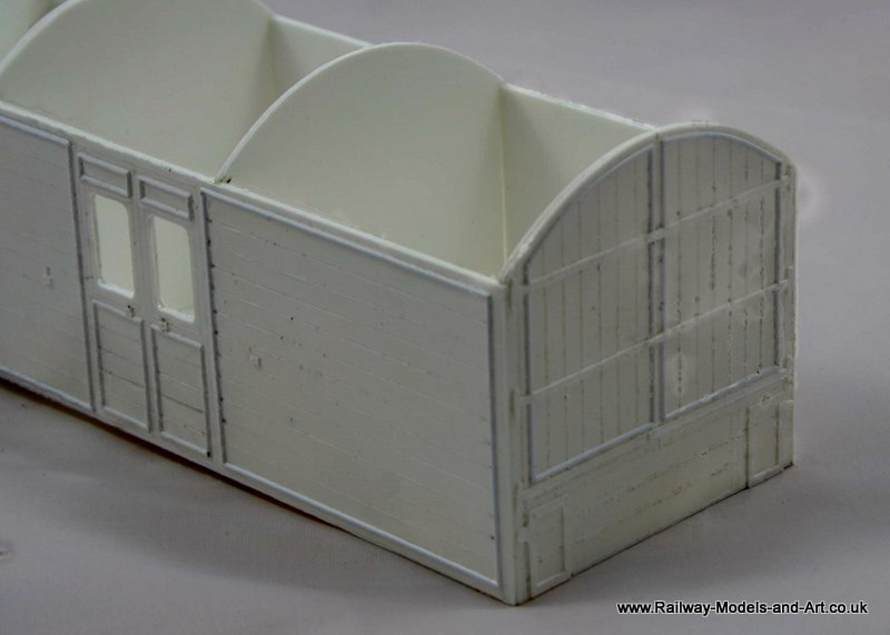
Kirk 51 foot All 3rd – interior details

Kirk 51 foot All 3rd – interior details
While the painting of said passengers (particularly the faces) isn’t as good as some, I am pleased with how they have come out and they will certainly pass muster inside the gloomy interior of the coach once matt varnished.

7mm scale seated passengers
If you wonder why they are sat above the box instead of on it, that’s because I have inserted a length of plastic rod to enable me to old them while painting and and it will help in making them securely fastened to the seats when fitted.