A little discovery here, having made the replacements parts yesterday afternoon was all about fitting them. Besides fitting the castings I started to fit the small pieces of etch that represent the backing plates for the rear steps and those just above the foot plate on the rear of the tender.
MOK 8F This is where it fits
Once I had added them I noted that there was quite a big intermittent gap along the bottom. I read and re-read the instructions and couldn’t see where I had gone wrong. There are not too many bits of etch left and one of them that I couldn’t find a home for is part 146. After much head scratching I worked out that although completely omitted from the instructions it fits as outlined in red on the image below.
MOK 8F Part 146- Not mentioned in the instructions
This is on the top side of the tender footplate (thankfully at this point I had only retained it by the tabs so it was easily removed). As if omitting it from the instructions wasn’t bad enough, there are no positive locating marks and in this photo I have it slightly too far towards the tender rear so I need to take it off and move it back a touch or the tender body won’t sit down and close the gaps.
What was I saying about soldering allowing you to take it off and adjust it…
Wow, 2018 since I last looked at this. No wonder Chris is muttering.
Any way I picked it up again yesterday and I started by making a couple of replacements for castings and turning the tank vents so that they at least sit flat and vertical to the tender top plate.
MOK 8F Whitemetal castings
These are the water scoop dome and brake cylinder. The latter is oval in shape and the former quite badly pitted.
MOK 8F Replacement turnings and cleaned up vent pipes
Replacements machined and since this photo was taken fitted.
After updating the Princess Firebox my thoughts turned to some actual modelling and I decided to build the next field gun. Another cheapo kit from Emhar (I also found out that Emhar are part of the Bachmann group so not too far away from Railways after all). This one cost a little more at £12 but still good value in my opinion.
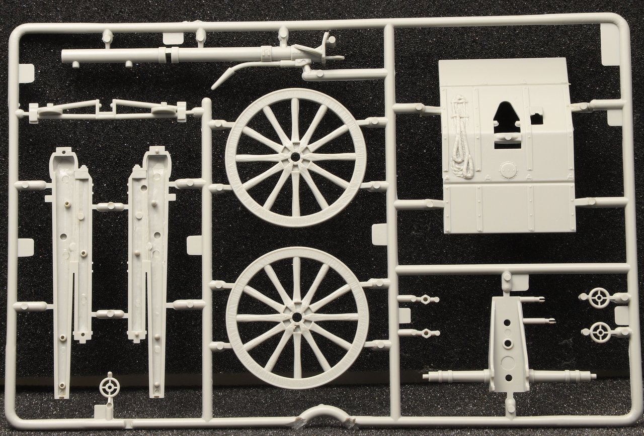
There are only 10 parts to the gun itself (there are 3 crew members provided too).
Emhar WWI British QF 18 Pounder Field Gun – Sprue FrontEmhar WWI British QF 18 Pounder Field Gun – Sprue Rear
This one comes with hand wheels so no need to make them.
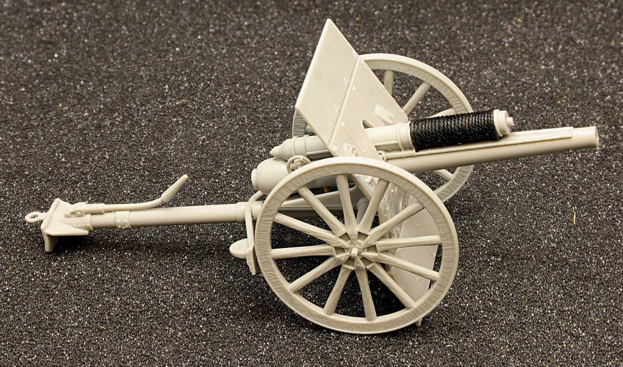
Construction was quite quick and besides cleaning up a bit of flash there weren’t too many improvements that I could make.
I cut off the pin which represents the elevation screw and added short length of 10ba stud an improvement that can barely be seen once assembled but I know it’s there. The only other improvements were adding cord to the recoil tube to represent the rope that is visible on most photos that I have seen and to cut a representation of the recoil slides. these are just moulded as a flat plate.
Emhar WWI British QF 18 Pounder Field Gun – Recoil SlideEmhar WWI British QF 18 Pounder Field GunEmhar WWI British QF 18 Pounder Field GunEmhar WWI British QF 18 Pounder Field Gun
I also drilled out the barrel to scale size.
I did consider trying to remove the moulded rope from the front of the Gun Shield but I wasn’t sure that I could get it off and replace it without making a complete mess. So I will endeavour to improve it with paints.
Emhar WWI British QF 18 Pounder Field GunEmhar WWI British QF 18 Pounder Field GunEmhar WWI British QF 18 Pounder Field Gun
One thing that I am struggling with is the lower plate of the Gun Shield. As supplied it seems to big (Unless you bend it forward as I have in the photos, it stops the barrel from seating on the carriage). All the photos except one, that I could find, show the gun without the bottom plate of the shield. The one that I have is taken from the rear and to one side so although the bottom plate is in place it’s not easy to see it if is indeed a bit shorter than Emhar have portrayed it.
I had made the amendments to make it fit to the footplate and sent off an stl file to be printed when someone on the GOG forum mentioned the front corners of the firebox. Initially I had planned to leave them as they were, but the same gent popped up a really clear photo of the firebox corners, so I revisited them this morning.
I have done some oil pin washes and I am finally calling this one finished, or at least until I get around to building a limber for it.
Emhar WWI FK96 German Field Gun – FinishedEmhar WWI FK96 German Field Gun – FinishedEmhar WWI FK96 German Field Gun – FinishedEmhar WWI FK96 German Field Gun – FinishedEmhar WWI FK96 German Field Gun – Finished
Next up will be the British WWI equivalent the 18 Pounder QF which is another cheap and cheerful Emhar kit which I hope that I can improve upon.
It was kindly pointed out over on Western Thunder that the rear washout plug on the right hand side was obscured by the boiler band. A detail that I had missed. Domestic stuff got in the way yesterday so I have only just had time to look at it.
I still need to do the check and correct against the footplate, next job hopefully.
I got the last of the details added to the drawing yesterday and now it just needs a tidy up of the sketches and the front end checking and adjusting so that it will fit on the kit footplate.
This week has mainly been about returning to the elephant in the room, the Firebox. There had been some discussion on Western Thunder some time ago about issues with the resin casting and I must admit I didn’t get ‘it’ and after a (very!) rudimentary measure up, it didn’t seem far out so I left it at that. Fast forward to last week and Nick Dunhill posted on my thread on the GOG forum and mentioned how far out his had been on all the ones that he built (he built four in total) and how much work it had been to rectify the problems.
The talk also mentioned a whitemetal cast firebox produced by DJH for Gladiator (prior to David and Trisha buying the range). After seeing the discussion the guy that I am building it for rang me and told me that he had one of the Gladiator/DJH fireboxes which he would send me.
Once I had it in hand, I imported some GA’s into Fusion from the Wild Swann book scaled them and started to compare the castings to the real thing.
Once I had done the comparisons it all clicked into place.
Because the ends of my casting were at 90 degrees to the footplate I thought that I had better castings once I realised that Nick had lowered the front by circa 2mm and raised the back by another 1mm it made sense why his front and rear face were no longer at right angles to the footplate and why the subsequent chopping and gap filling.
Nick’s advice was to scratch build one or get Mick Davies (of Finney7) to draw one up and print it for me. I have initially opted to have a go at drawing it myself.
This is where I got to after the first session. Subsequent study made me realise that I needed to bring the curve under the front down a bit.
After my second session I had this – I did a short video capture of Fusion as being easier than taking multiple renders which I was struggling with.
Once all the boiler band cleats were made I fitted those to the boiler section that I could. There is another to fit to the firebox but more on that in another post.
There are three boiler bands on the boiler itself and the two front ones have the band cleat underneath the boiler while the one in front of the firebox is fitted on the top as is the one on the firebox.
Another fact that I picked up from the GA in the Wild swan book is that on the combustion chamber boilers which were fitted to 6206 at this point in her life was that the band cleats were slightly offset to one side.
David Andrews Princess Royal – Boiler Band Cleats fittedDavid Andrews Princess Royal – Boiler Band Cleats fitted
This is the bottom of the boiler.
David Andrews Princess Royal – Boiler Band Cleats fitted
I entered the loco part of my Princess Royal Build in an online forum competition and although I didn’t get it finished by the close of the competition no one else did either so as a result of a members vote I won first prize.
Since my last post I have been adding some chipping effects (another first for me, unless you include some miniature vintage signs that I chipped the edges of some years ago for railway diorama).
I still need to add pin washes with oils and some mud on the carriage and wheels.
Emhar WWI FK96 German Field Gun Chipped and DirtiedEmhar WWI FK96 German Field Gun Chipped and DirtiedEmhar WWI FK96 German Field Gun Chipped and DirtiedEmhar WWI FK96 German Field Gun Chipped and DirtiedEmhar WWI FK96 German Field Gun Chipped and Dirtied
Emhar FK96 Field GunEmhar FK96 Field Gun
Still some way to go but I am happy with progress so far.
Moving on from the last post has involved a bit more micro surgery in the form of boiler band cleats.
You do get etches for them in the kit and the suggestion is to tie them together with a length of 0.5mm wire. Me being me I had to make some nuts to go on each end…
Fitted the window stays above the windows in the cab these are extra from now extinct HobbyHorse Range.
David Andrews Princess Royal – Hobby Horse Window StaysDavid Andrews Princess Royal – Boiler bands and ChimneyDavid Andrews Princess Royal – Boiler bands and ChimneySeam Line
After my initial post on the Guild forum a fellow member contacted me by PM and showed me photos of how he had articulated the outer section of the cab doors as well as the inner. Never one to shy away from the challenge I modified them the cab doors this afternoon.
Not only is Chris’s suggested method very simple, it’s also very robust.
David Andrews Princess Royal – Folding cab doorsDavid Andrews Princess Royal – Folding cab doorsDavid Andrews Princess Royal – Folding cab doors
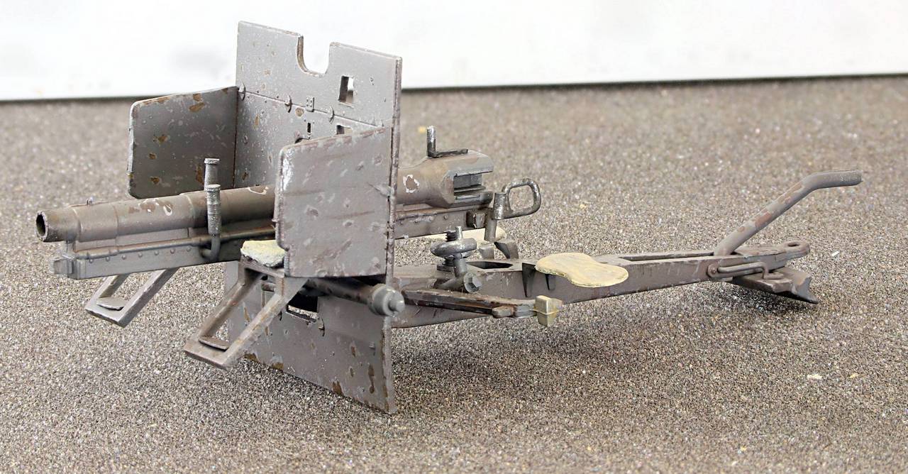
Last thing last night I managed to get a coat of home brewed Field Grey on it. I didn’t have any proprietary Green Grey (although I do have Vallejo Grey Green it looks far too dark being almost black) so I used Vallejo Air Dark Sea Grey with a few drops of Vallejo Air Olive green to add the green tint to it.
The wheels are just push fitted for now.
Emhar WWW! FK96 German Field Gun – Field GreyEmhar WWW! FK96 German Field Gun – Field GreyEmhar WWW! FK96 German Field Gun – Field GreyEmhar WWW! FK96 German Field Gun – Field Grey
A bit more done at the field gun and it’s ready for paint now I think.
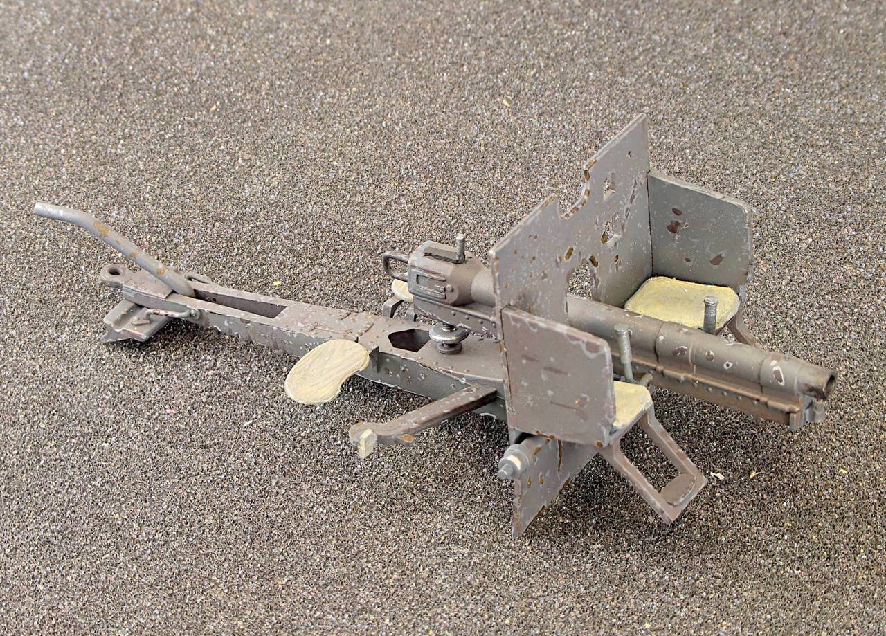
Photos of the real thing show a couple of levers at the front. so I added those from small brass turnings and rod. The one on the right (left as you look from the front) isn’t strictly accurate as it had a more complicated mechanism that it was attached to but I can’t make it out clear enough to models it.
FK96 Field Gun ready for paint
Next I made what I think is the trigger. Emhar had a representation visible in earlier photos but it was again placed on the centre line and a bit undernourished. It was also curiously hollow with an open side which I have represented from filed down microbore tube.
FK96 Field Gun trigger mechanism.
Last but not least on the left of the carriage behind the shield was a hand wheel, presumably somehting to do with adjusting the sighting.
I turned one up on the lathe and I was so pleased with it I decided to replace the ring of plastic that I had added to the elevation screw with a proper turned wheel tapped 10ba.
Hand wheels and mountings
Shown with my giant sized 5 pence piece for scale…
Hand wheels and mountingsHand wheels and mountingsFK96 Field Gun ready for paintFK96 Field Gun Ready for Paint
Since taking the photos I have added some brass chains to the rear of the gun shield.