Today was quite satisfying in so much as I got the brake beams assembled and I also got the new brake cylinder and the front cross shaft fitted which in theory leaves the brakes, the rear coupling and the small etches and pins which fit on the outside of the outer frames adjacent to one end of the springs where they represent the ends of the brake hangers.
The Proxxon mini pillar drill earned its keep drilling all the holes for the link pins on the cross beams.
Brake Cross Beams
Next, I fitted the brake cylinder and the front cross shaft. The shaft and the castings which attach to the brake pull rods are still loose until I work out the correct orientations of them.
Brake Cylinder and Cross shaft fitted
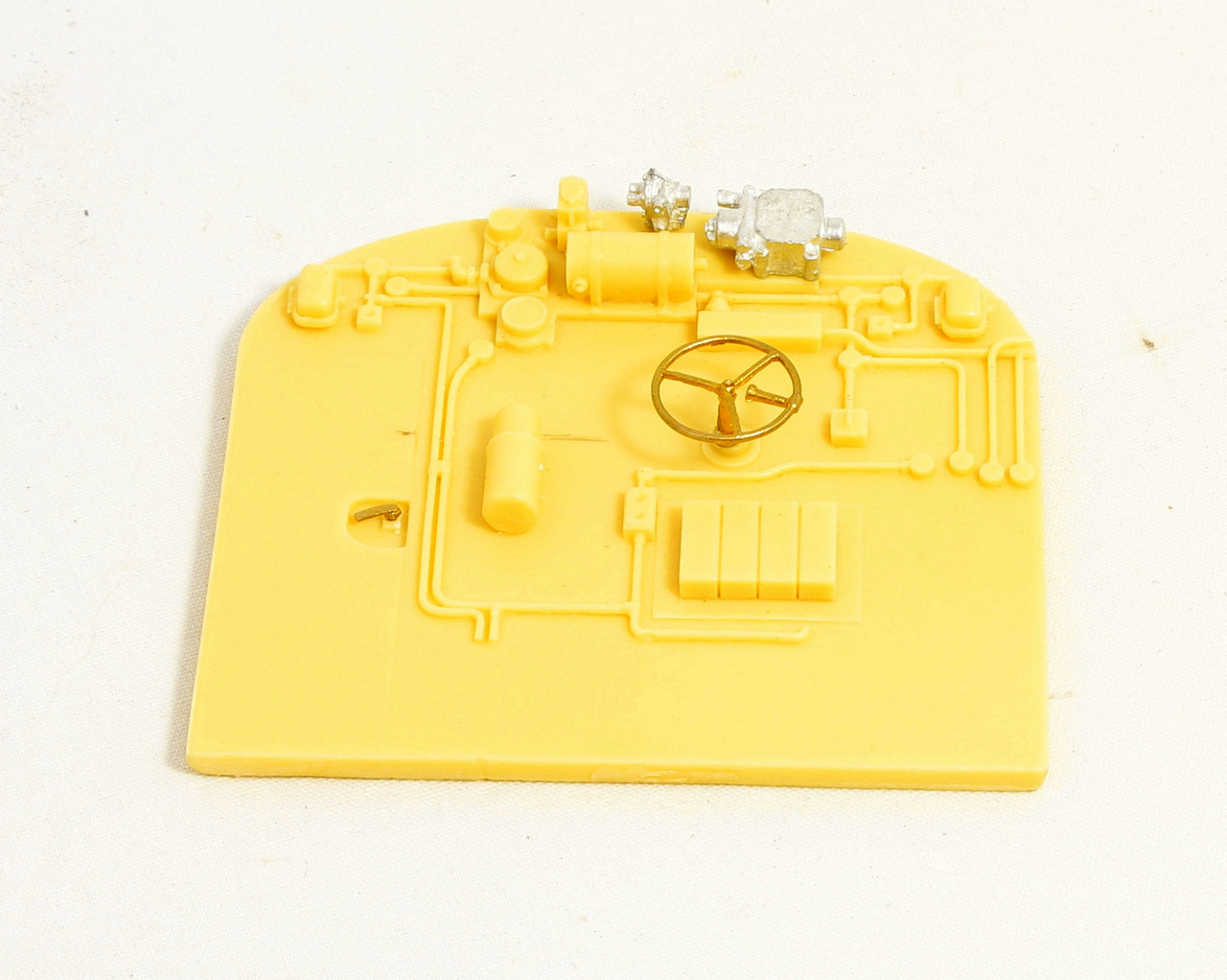
Lastly a close up of the new brake cylinder.
Replacement Brake Cylinder
Making and fitting all these extra parts has renewed my enthusiasm for the build which was waning a little.
Having sorted the water scoop thoughts turned to the brakes as being the last major items to fit. This is where life got a little interesting. As I mentioned previously the kit is “borrowed” from my Just Like the Real Thing, Rebuilt Scot kit. According to the JLRT instructions, the brakes for the Royal Scot tenders differed from the usual Stanier tenders being much simplified.
Below is a snip from the instructions illustrating the simplified version.
Fortunately, JLRT did provide an etch for the linkages, albeit they didn’t include any cross beams. Presumably this was intended for use with another kit which included a Stanier tender but I can’t think of one in the JLRT range.
This left making up some cross beams. I started with some 2mm brass rod and having cut three lengths I turned a spigot on each end to fit through the holes in the brake hanger castings.
Beginings of Brake Cross Beams
Next, I created a small jig which is essentially a rectangular block to hold the cross beam rods to allow me to machine parallel flats on each end.
Milling Brake Cross Beams
Finally, for the session, I machined a replacement brake cylinder.
Picking up from my last post, I have been slowly but surely working on the remaining tender details. The upper body is complete with just some small etches to be fitted to the outer chassis plates.
Then on with the fitting out of the inner chassis. First came making up the fun packed water scoop linkages.
JLRT Stanier Water Scoop Linkages
Then the more fun packed threading of them through all the various parts and holes in the inner chassis before soldering things together.
This is where the experience of having already done it once on the MOK tender came in handy. I found it much easier to do second time around because I knew where everything was meant to fit.
Water Scoop linkages fitted to JLRT Stanier TenderWater Scoop linkages fitted to JLRT Stanier TenderWater Scoop linkages fitted to JLRT Stanier Tender
While awaiting the opportunity to make a start on cutting the gears. In spare moments, I have been having a play with the Gear Generator add in, in Fusion 360.
I decided to create myself a working drawing of the Shogun gear replacements that I need and I was quite pleased that Fusion came to the same conclusions about size etc. that helpful fellow modellers (who are far more experienced in the subject than I,) had already worked out.
Still making slow but steady progress on the welded tender. The upper works are now complete and I am in the midst of making up the water scoop linkages. It taken a couple of days to cut all the castings from their sprues and clean them up al the while working out where each bit goes. I think that I have it pretty much figured out now but I still need to double check the front linkage to be sure where it fits.
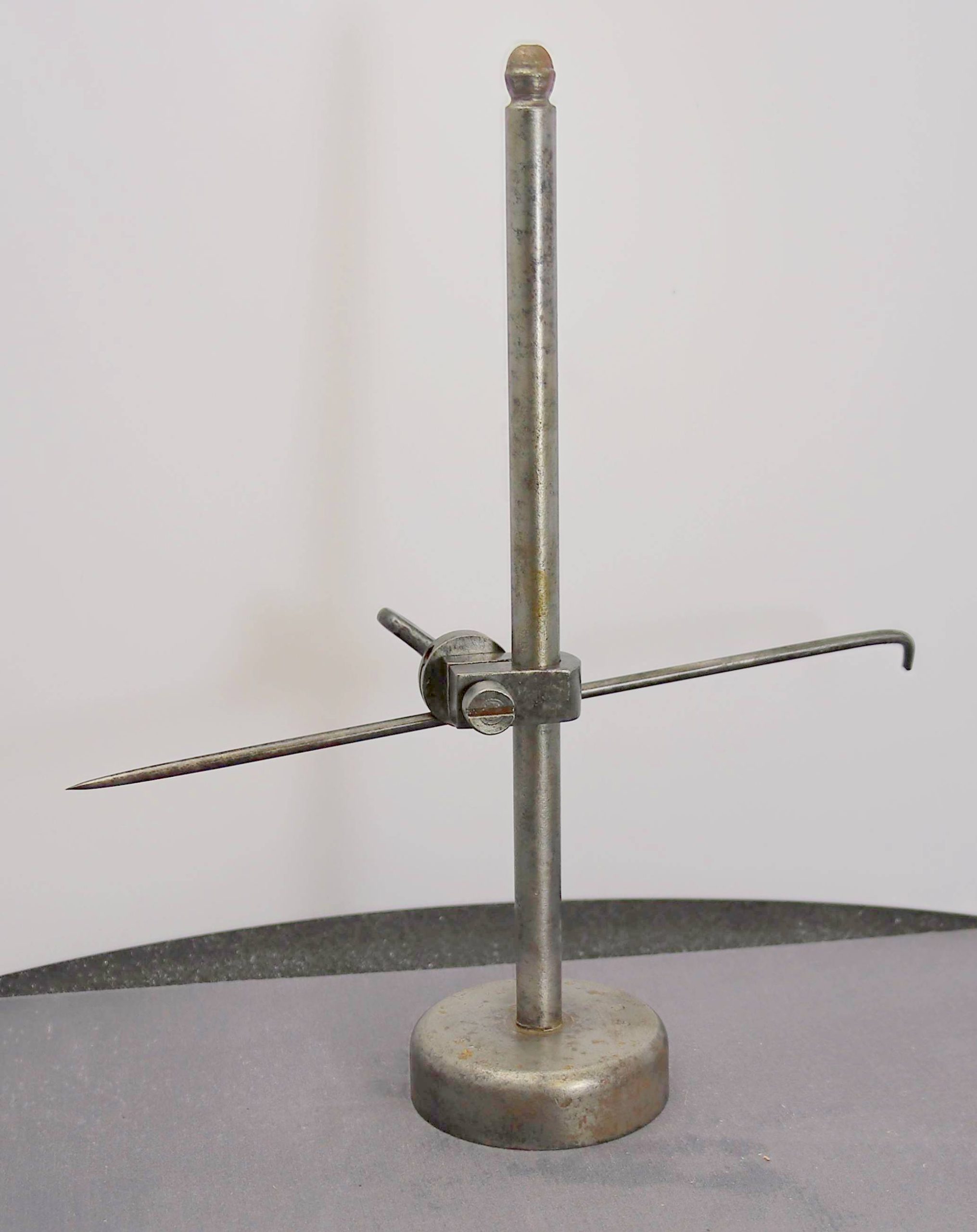
I bought it along with a number of other hand tools which I have subsequently restored over the last year. But I actually bought the job lot on the basis of it containing this. My idea was to make a lathe Tool Height Setting Gauge from it loosely based on the GH Thomas example which is marketed as a kit by Hemingway Kits.
A fellow parish councillor recently gave me a few pieces of steel one of which was perfect for making the two height setting arms.
While chatting to a friend on the phone last night I said that I wasn’t going to post any more on the tender because it’s really a repeat of what’s gone before on build but then today, I had a hiccup in proceeding so I thought it worth sharing how I got out of it.
The kit provides two of these Windlass castings for the water scoop and brake standard.
JLRT Windlass Casting
As I was cutting the second one off the sprue it pinged off into space and despite searching the workbench top, I couldn’t find it. Having no idea which way it went, I don’t know where to start looking.
So, I decided that it wouldn’t be too big a job to make a couple of replacements to match. Staring with some 1.5mm brass rod I cross drilled it and turned down the end.
The machined spigot prior to parting off
Parting off such a thin piece on the lathe was bound to be a disaster so I opted to cut it off with a piercing saw while it was still held in the collet and… you guessed it, that too pinged off into the swarf and was lost for ever.
Having set everything up it was a few minutes job to prepare some more. This time I played it safe and held the main stock in one pin vice and the part to be cut off in another.
Holding the tiny pieces for parting off
Having established the workflow I decided not only to make the two that I needed but to do a few more for the spares box too. The ones I need for the tender need quite a short stem but I also did some with longer stems just in case I need them for upright brake standards in the future.
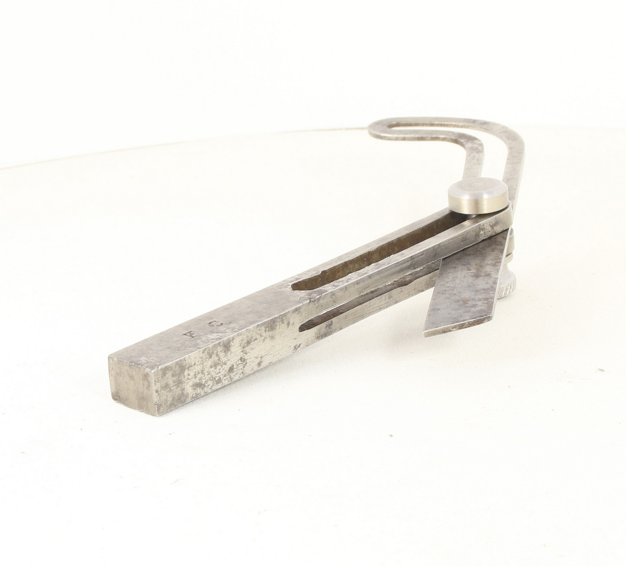
Back In October 2024 I won a job lot of Engineering tools via eBay. When they arrived I was reasonably certain that they were apprentice pieces all made by the same gent and stamped FC. At the time I cleaned them all up and I restored most of them in terms of parts that were missing. One final piece a sliding curved bevel worked but it wasn’t possible to tighten up or slacken off the thumbscrew. I tried several times in the intervening 11 months but did manage to budge it no matter how aggressive I got, I didn’t manage to budge it. In the end a week or so ago, I just lost patience and hacksawed the thumbscrew off.
I machined up a new thumbscrew and it worked but the stud part looked a bit undernourished so I made a second stud that I was happy with. I also spent a bit of time on the slides to ensure that all the parts move freely along the full length of travel.
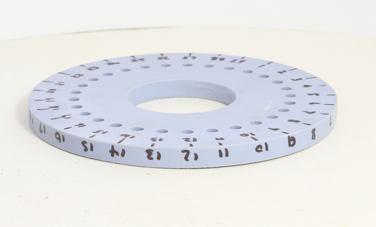
A friend and fellow Guild member fell soft and offered to have a go at 3D printing my 29 hole division plate.
It turned out really well with all the indexing holes fitting perfectly and the main bore just requiring a little scraping with a 3 cornered scraper to enable it to ease onto the shaft.
Had I been quicker on the uptake I might have added the numbers to the STL file before sending it but it only occurred as I was fitting it to the Spin indexer.
For those that don’t know what a Spin Indexer is, this is mine fitted with the 29 hole division plate.
The eagle eyed will note that the label says ‘5C’ 5C is the type of collet what these indexers come equipped to accept as standard. I don’t have any 5C collets nor am I likely to make use of any so when I saw the Spin Indexer offered at a discount price already fitted with a 5C to ER32 collet adapter I decided that I could make wider use of ER32 collets so I bought the indexer and a set of ER32 collets. Since then, I have added an ER32 collet chuck for my lathe so now I can use the ER32 collets in both the lathe and spin indexer alongside my more often used ER25 collets
This means that I am now set up to have a go at cutting the 2 x 29 tooth gears that I need for the Shogun gearboxes. I am still doing carer duties and Chris doesn’t have her stitches out until next Wednesday. So it will probably be later next week before I take the plunge and have a go.
Discussion over on my gear cutting thread on Western Thunder has had input from several members who are experienced in cutting their own gears and part of the discussion was around worm and wheel gear sets.
We discussed that it is possible to use a length of say M6 x 1.00 threaded stud to make the worm and use an M6 x 1.00 tap in the lathe chuck to cut a wheel with at least one member having done this in the past. having seen this done in a video sometime ago it was of interest. Then I used a thread gauge to check a Roxey Mouldings Worm and Wheel gear set which came with one of their fold up gearboxes. The metric 1.25 thread gauge fits perfectly but the diameter of the worm is 6.3mm so I think that it’s actually more likely to be 1/4″ x 20TPI rather than M6 x 1.25
We also discussed that using a BA profile of 47.5 degrees would be better than using the standard 60 degree of a metric or US imperial thread. Having checked my BA thread chart I was a little surprised to find that 0BA is 6mm and has a 1.0mm thread pitch. The key difference between Oba and M6 is the angle of the teeth being 47.5 as opposed to 60 degrees. I have lots of 6mm bar recovered from scrap printers and toner cartridges so some trials are in order.
I have been asked if I will do a ‘gear cutting 101’ for those with little understanding of gearsand gear cutting (I count myself amongst them… ) So I will endeavour to share what I have determined so far.
Gear sizes/measurements come in two flavours (as you might expect) Imperial and Metric. The descriptions for these are:
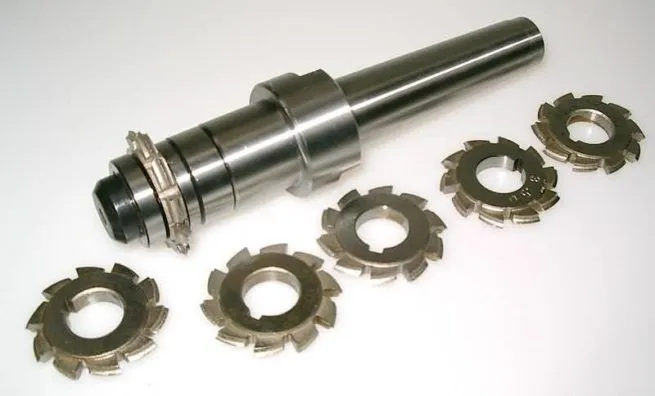
Involute DP Gear Cutters ( DP standing for Diametral Pitch inch size) These come in two pressure angles 14.5 degrees and 20 degrees
Metric Module (MOD) have a declared pressure angle of 20 degrees.
Each Involute DP or Module set is made up of 8 cutters which perversely, the number for each type is reversed from each other
Having determined with help that the missing final drive gears were MOD 0.3 and that MOD 0.3 is a bit fine for 7mm models I bought from Chronosa set of MOD 0.5 gear cutters.
I also bought a single MOD 0.3 No5 cutter which will cut 26-34 teeth from a company in Japan called Gavan Tools but no great surprise that once despatched and I started tracking it, it was coming direct from Shanghai China. That said, the tracking information provided was excellent and it arrived safe and sound.
This is the same image with a little more contrast to all you to better read the details
In my last post I mentioned that a fellow Guild member had a couple of new boxed examples off the Shogun units. He kindly shared some photos of them which with his permission I will share here so that you can see what we are aiming for in the end.
This is the accompanying data sheet
You will note the bit about a ‘special’ axle. I checked mine and the bushes are under the standard 3/16 axles that we traditionally use so I plan to drill and ream mine out to 3/16 making the drive gear to suit.
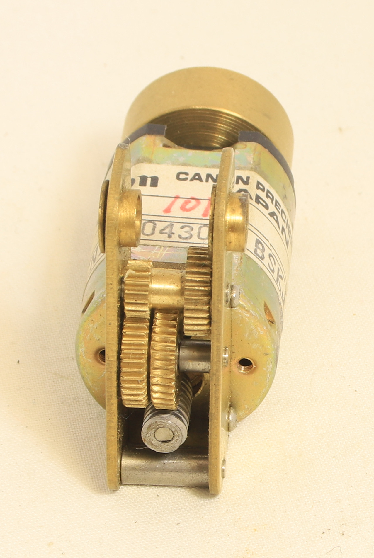
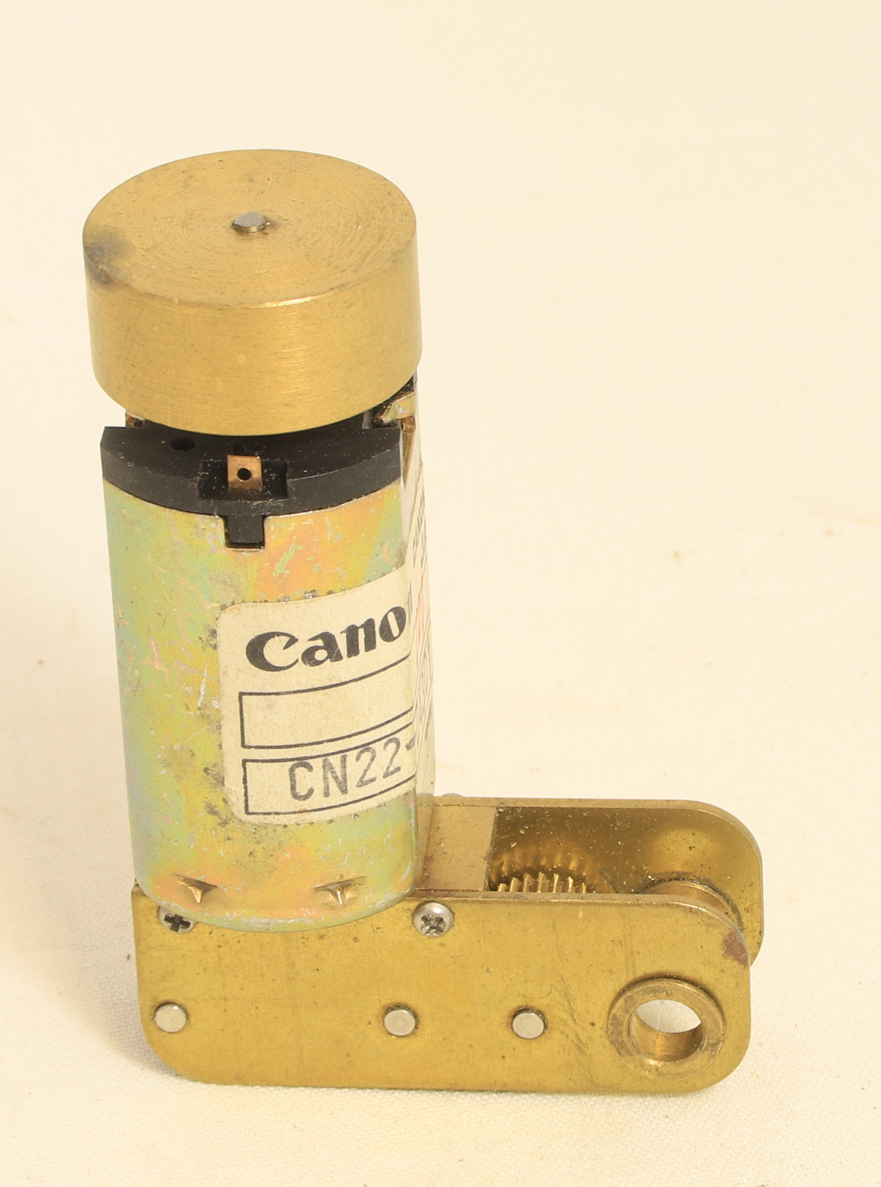
At Guildex (Stafford) I bought a couple of Tower Models 7mm O Gauge ‘Tower Power’ Shogun 5-Pole Canon Motor w/ Multi-stage Gearboxes. Although I didn’t know that’s what they were at the time, the price was right but I did note that they were each missing their final drive gear. In my view, the Canon Motors and fly wheels alone were worth the £25 each that I paid for them.
Enquiries on Western Thunder and the GOG forums, identified the product as described above and subsequently contacting Tower Models confirmed that there are no spares available.
One member of both forums happened to have a couple of the same gearbox units new and boxed he was very helpful in confirming that the gearboxes or at least his boxes were 25:1 ratio he also counted the number of teeth and confirmed that there were 29. From further discussion it also revealed that San Cheng who produced them for Tower also used the same gearbox side frames for an 18:1 version of the gearbox using slightly different idler gears.
We ultimately came to the conclusion that the final drive gears are 29 tooth the Module is 0.3 and the diameter of the gear is 9.26mm
Finally the bit that you have all been waiting for, this is what it looked like when it went for paint. I confess that being so big I really struggled to get it all in shot and in focus
Fred Phipps WarshipFred Phipps WarshipFred Phipps WarshipFred Phipps Warship
I always knew in my gut that I wasn’t going to be able to live with them so a couple of days after my last post I ripped the battered sides off and cut some more from 10 thou nickel sheet.
MOK sides removed
Ironically the side that went on okay came off in pretty good shape too.
This was the basic sides cut out ready for detailing before fitting.
I managed to salvage the handrails and handrail knobs from the damaged sides and it was a simple enough job to fit them to the new sides. Initially I was planning on adding the side then fitting the beading but in the end I also opted to fit them first while the sides were manoeuvrable.
I also remembered that to make the MOK rear sheet match the new scratch built sides, I would need to remove the half etched upper beading and replace it. Being half etched it was soon removed with a few strokes of a file. I fitted a length of 0.7mm half round beading along to the rear and left each side a bit long to blend in when the sides were fitted.
I didn’t take any photos of the sides before I fitted them but this is the creased side after being replaced.
Creased side replaced.
The other side had to be replaced to match.
Good side replaced to match.
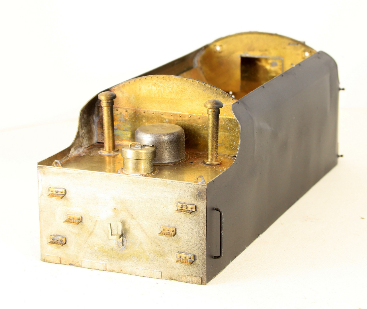
The rear beading and other details such as the fire iron tunnel and tank vents were also fitted.
Rear beading reinstated
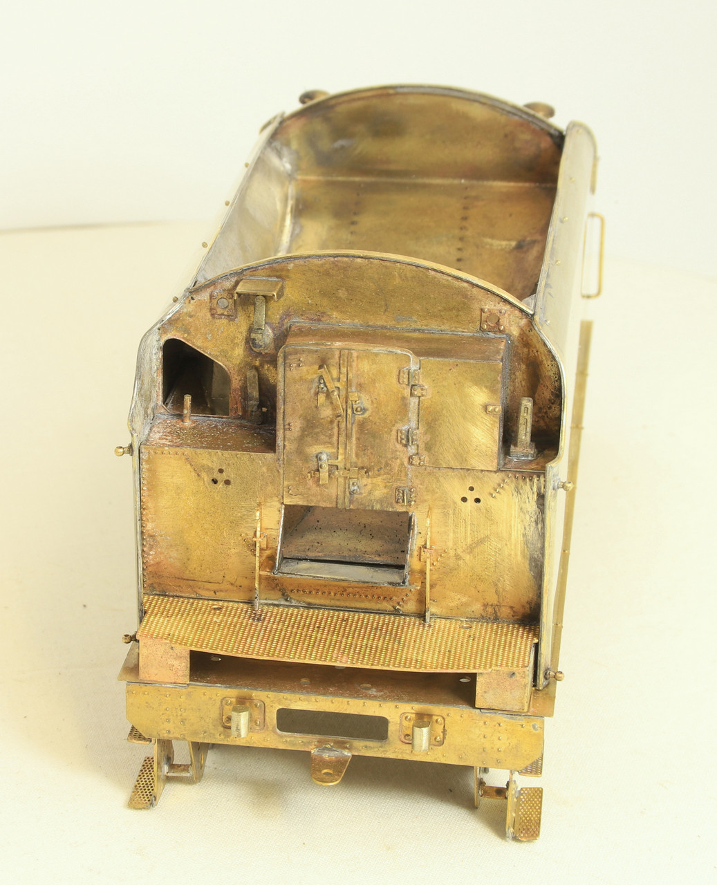
I have also made start on adding the other details to the front.
Front end details being added
While much muttering had ensued, in hindsight I am glad it happened in a way because I feel the new sides look much better than the half etched MOK ones did on this tender.
The right hand side buffer at each end as you are looking at it from the front has a step attached to it. I had made up the steps back in 2017 but hadn’t attempted to fit them to the buffer castings and I am glad I didn’t because I didn’t have a mill back then. On the basis that there are a couple of small gluing points, the attachment to the buffer casting would be the crucial bit. as they cam I couldn’t workout how I might get them all attached consistently while still maintaining the integrity of the steps. The solution was to mill a small flat on the bottom of each buffer casting to give a good base to solder to.
At this point I was left with these castings which I had no idea where they fitted. A quick email to Fred pointed me in the right direction. Although he told me where they fitted he said refer to photos. But on all the photos that I had at the time (I have kindly been provided with a number of really useful photos since I started posting the build by a kind Gent on RMWeb) the cab steps obscure them so they are not visible.
I also had a photo of a bogie which had been removed from the loco but although they fit on top of the springs they had been removed so that photo while clear on may other details didn’t help.
Finally this is them fitted to the springs.
Being Gauge 1 I also took a punt on the fact that it would be battery powered so I didn’t attempt to fit any pickups before it went for paint. It turned out to be a good guess.
I was feeling quite pleased with myself having managed to move the fold in the thin material without it creasing so I went ahead and soldered the first side on. Not having learned my lesson from a similar experience when I built the Class 5A a few years ago I tinned all the bit of the inner cage and the sides and lower section of the curves of the bulkheads.
Then using the RSU I spot tacked the side in place but struggled to get it to stay in place and ended up being a bit heavy handed which resulted in a number of creases.
Now they do actually look a bit prototypical in that I have seen lots of photos of tender with seams/panels and creases and dents visible at certain angles but it’s not what we tend to model. My other question mark besides can I live with it is that during my modelling period this tender would be relatively new and I am not sure that the premise of a wartime Friday afternoon at Swindon is enough of an excuse to leave it be.
Not the easiest things in the world to take photos of so in the end I squirted a bit of primer at it to get a better view of what it might look like after paint.
Moving steadily along next I did the cab detailing and this is where things started to go a little pear shaped.
The castings in the kit are excellent with the minor exception of a couple of whitemetal ones which would do at a pinch but I made new ones because they were very undersized.
The instructions on the other hand are very basic. I am sure that if you are a diesel modeller they are probably quite adequate but for someone who has no idea of the subject matter I really struggled. I did manage to find a number of photos but of course they don’t show you everything. In fairness to Fred the sketches included do show where to add much of the detail but where I went wrong was the cab interior. The sketch shows how the control desks are laid out in the cab and the seats in relation to the floor etc.
Warship Drivers consoleWarship Secondmans cabinet
They fit together like this, so as you might expect the first thing that I did was stick them together with epoxy. Once they were dry next day I test fitted them in the cab and realised that there was no way that they were going to fit. I dropped Fred an email to ask what I was missing and he kindly gave me his phone number and said give me a call and I will explain how they fit into the cabs.
Warship Cab front consoles
They fit like a 3D puzzle, you slip one of the desk in first and hook the angled section at the edge of the desk over the window ledge. Then you slip the second on in and do the same, but you need to have this a little way behind the first desk to allow them to fit side by side then you slide the two together and they hold each other in place.
Warship Bulkhead
I made a couple of turning s for the hot plates as I struggled with the whitemetal castings. I also soldered up that loose joint before fixing them to the bulkhead just to the left hand side of the brake wheel.
This morning I was getting ready to fit the sides when I double checked the bends against the sides of the inner cage and realised that I had my bends a little too low on the side so the tender side would sit flush without having to force it into place. Past experience has taught me that while you can force items into place and then solder them the odds that the solder under tension will give at some point in the future so I elected to do something about it before soldering the sides on.
Bending kit etches has become a bit topical over on Western Thunder so I thought I would go into a bit more detail about how this came about and what I did to get around it.
As supplied the Just Like The Real Thing Stanier Tender kit that I am using had riveted sides which came with some little etched tabs to guide you where to make the top fold.
You can see the small tabs with the red lines against them in the image below.
By laying one JLRT side over the replacement MOK welded side I transferred the bend lines over. Unfortunately these lines create a guide rather than a specific place to bend and I had got it wrong. Now being half etched and nickel getting the bend to move was going to prove a little tricky. However I reasoned, that worst case scenario I could use the flat JLRT sides as a template to cut out some replacements from 10 thou nickel sheet if I made a mess of things.
The first thing that I did was to ease the fold line that was too low. I did this by carefully beating it with a rubber mallet, using a thick steel tube filled with lead as a makeshift anvil.
Rubber Mallet & Makeshift Anvil
Note that I was using a curved surface rather than a flat one. The idea being to ease the bend back into a shallow curve rather than trying to flatten it completely and risk leaving a crease.
Next I measured the tender side to see where the start of the bend should actually be rather than working to a guestimate between the two previously marked lines.
Measuring the bend location
On one side it was 4.5mm at each end and the second side it was 4.5mm at one end and 5mm at the other I transferred these marks to the outside of the MOK tender sides so that I could drop them in my folding bars and still see the line as I positioned it ready for rebending.
You can just make out the middle line in the image below.