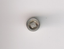
While I was in the midst of making the washout plugs for the 8F I had a look through the kits stash to see if I needed any for other models while I was on with them. most are covered but I do need some for my B16. These are slightly different in that they are inset with a raised rim. Having made a number of spares it was a relatively simple job to turn half a dozen or so collars that the washout plugs would fit into.
Washout plugs with collars
The idea being that I will solder the inner plug into the collar then cut the base off allowing them to be fit into the loco fire box. In the meantime they are now in the B16 box, in a little bag awaiting their day to shine
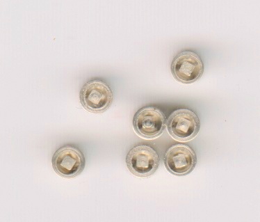
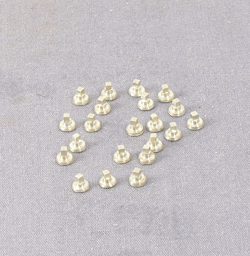
Ian Allen, fellow Guild member and font of knowledge for all things LMS kindly pointed out that the cladding band on the firebox only had the bottom four or five fixings, so the rest need filing off the firebox casting. He posted a photo showing his example and wile looking at it it reminded me that I still needed to do something with the washout plugs. I knew that I needed to do them but seemed to keep overlooking them as I progressed with detailing. So yesterday I got stuck in and made some.
My initial attempts were with a collet block but they came out asymmetrical and I couldn’t understand why so I fitted the spin indexer to the mill and tried again. it was at the point that I realised that my bit of brass rod was bent – this particular piece of rod has caught me out before…
I checked stock and found a piece of similar sized (3mm) nickel rod and tried again. All was well so I got stuck in and set up a mini production run and a couple of hours later I had enough for this loco plus a few spares.
They are designed to be soldered in from the inside. So the next job is to drill out all the holes and fit them before starting to fit all the oilboxes.
As a consequence of the need for miniature studs for the return cranks on the 8F I decided how hard could they be to make.
I started as I would make miniature bolts by turning down the end of a piece of 1.2mm nickel rod to 0.8mm at either end (to make two at a time from each piece of stock). Then I removed them from the lathe and popped them in a hex headed pin vice to file the hex flats on. If I did a production run which I may at some point I would have set up the spin indexer to make them all consistent. As it is they are okay but not perfect.
Then I came to put them back in the lathe to turn the short length of dummy thread which protrudes beyond the nut. This is where I started to struggle a little. Even though I had sharpened the cutting tool I was still getting a bit of deflection of the stock.
Then I remembered that just after Christmas in a Warco Sale leaflet I had bought a live centre with multiple interchangeable points.
This got me wondering if I could make another tip with a 0.8mm hole in it to support the tail of the stud while I turned the other end down to size before parting off.
This is what it looks like in the live centre. The taper isn’t a perfect fit but it’s under so little load that it isn’t an issue
Mini Stud Tail Support
For those struggling to visualise what I am talking about, I did a simple sketch
The MOK 8F is progressing albeit slowly. I have been working on the replacement JLRT tender which is coming together.
The welded tender rear plate needed rivets punching out and I had to make another anvil to make sure that the spacing was correct. Sadly I made a complete hash of punching them out, only getting one set out of 6 where they should sit.
After much muttering I made the decision to flatten the punched rivets and file off the reamng stubs. Then I riveted a piece of thin brass along one edge with blocks of three rivets at the correct spacing. Between those I left a space so that I cold cut them to fit. I fitted the JLRT steps first, then soldered on the riveted plates above them to compete the illusion.
MOK-JLRT Tender Rear
The casting for the water gauge supplied by JLRT was whitemetal and seemed very big so I machined another one based on the one supplied with the MOK tender
I still need to solder it in place but it looks the part.
JLRT Tender Front
I also started to add details to the tender front, I couldn’t resist trying to make the locking latch work by filing down a brass dressmakers pin to act as the pivot.
While searching for something else I came across a kit for an LMS Long Low by the long defunct Blacksmith Models.I had a quick look in the box and was pleasantly surprised to find that it contained a set of wheels presumably added by the previous owner. I bought it along with a number of other kits a few years ago before we move up to North Yorkshire. A closer look also revealed quite an interesting and I suspect quite advanced for its time underframe etch. I didn’t take photos of it in the flat but I was intrigued as to just how it folded up and couldn’t resist having a go.
Blacksmith Long Low Underframe
This is just folded without any solder applied yet.
For quite some time I have been steadily working my way through a selection of 3D printed NER wagons for a friend painting and lettering them. The painting was done over time but last week I got stuck into the lettering
NER R3 Coke hopperNER S4 Hopper WagonsNER D1 and D2 Bolster WagonsNER P3 and P4 Hopper WagonsNER P1 and P2 Hopper wagonsNER C2 Open WagonsNER S1 Hopper Wagons
Much of the lettering was done with some custom transfers printed by Precision Labels. They are nice and once you get used to them quite easy to apply but the font is a bit small in my view and could have done with being a couple of points bigger. They are also quite vulnerable to the lettering rubbing off when handling until they are over varnished. Still an interesting exercise as a I wasn’t too familiar with the various NER diagrams.
Completion of another long running build took place in the last couple of weeks during our arts and crafts sessions. This Diagram 129 was mostly complete only requiring glazing, guards grab handles and couplings to finish it off. I am not sure why I didn’t get it finished but hey ho.
LNER Diagram 129 Parcels VanLNER Diagram 129 Parcels Van
A couple of days ago I finished the painting of the brake van and then glazed it and refitted the buffers.
The result is quite unusual when compared with the normal SR brown or BR Grey liveries. Spray painted with Anitas Acrylics Sunshine Yellow and Vallejo Model Color Black. The interior was done with Vallejo Game Bone White and Model Color Medium Sea Grey for the veranda floors.
Connoisseur LSWR Brake van finishedConnoisseur LSWR Brake Van FinishedConnoisseur LSWR Brake Van FinishedS1280Connoisseur LSWR Brake van finishedConnoisseur LSWR Brake van finished
It will be on it’s way to it’s new home this afternoon.
Another session at the bench yesterday saw the remaining brake van ready for paint. With the addition of the final details such as buffer stocks, sandpipes and guard irons added.
LSWR Brake Van Ready For PaintLSWR Brake Van Ready For PaintLSWR Brake Van Ready For PaintLSWR Brake Van Ready For PaintLSWR Brake Van Ready For PaintLSWR Brake Van Ready for Paint
After all that I forgot to add that I also turned some replacement buffer stocks. Those familiar with Jim’s kits will know that to keep costs down Jim provides whitemetal buffers which can be sprung but it involves fitting a piece of spring wire through the back of the coupling hook and then to the rear of the buffers. Although I used this method on a few of my early builds having broke one of the cast heads of a buffer rather put me off the idea so now I add sprung buffers and I usually solder the coupling hook solid.
I had some spare buffer heads (kindly supplied by our very own Mr Moss as when received from NER Days they were unusable without further machining which Mossy isn’t equipped to do) which are fitted with 10ba nuts so the shank is a bit thicker than the 12 or 14ba that most comercial wagon buffers are fitted with. I did drill out one of the white metal buffer stocks and I did make it ft but the walls were very thin. I decided to turn replacements from some 14″ nickel rod. Although the finished dimensions were the same as the whitemetal examples the nickel replacements are much more substantial.
LSWR Brake Van Buffers
So now The van just needs these fitting, some sand pipes and coupling chains and a good clean up before painting.
On Bank Holiday Monday I took the one to be finished along to Harrogate show and again made excellent progress despite chatting to lots of people.
What I hadn’t realised at Redcar show is that although I had assembled parts 23,24, 25 and 26 into a sub unit and dry fitted fitted them I hadn’t actually soldered them in the second van. Sadly when I piked the van up to pack it away the sub assembly must have dropped off asI couldn’t find it at home when I discovered it’s was missing.
So I ended up scratch building a new sub assembly to replace the missing one.
I fitted a floor and then fitted the subassembly before fitting the rodding. Having prepared the parts before I went to Harrogate I did all the assembly during the show so didn’t get any photos of the subassembly after I put it together or without the rods in place. I replaced the two part etched crank with a piece of 10ba threaded rod (I have a number of short lengths from where I have shortened 1″ screws) with a wrap around that better represents the real thing.
LSWR Brake Van Brake RoddingLSWR Brake Van Brake RoddingLSWR Brake Van Brake RoddingLSWR Brake Van Brake Rodding
Although there is a plan view of how the brake rods fit the small fitting that fits the upper rod to the bottom of the van isn’t provided so I knocked a couple up from scrap etch. Bending and soldering those last two short upper sections of rodding in place really challenged the patience and it’s a good job I was in public or I may have expanded my Anglo Saxon dictionary…
For the last couple of weekends I have been demonstrating brass wagon building at a couple of shows so I took these along to see if I could make some progress on them. Surprisingly I did manage to make quite a bit of progress with both of these now up on their wheels with brake gear fitted. They still need brake rodding added and then details such as buffers etc. – I will take some photos once they are properly dry.
The plan for these was always to sell them when complete to fund something else and now that they are nearing completion I am starting to think about what livery to finish them in.
The good news is that they are now both sold, one as is to be finished by it’s new owner and the second to be finished and painted in a yellow light railway livery.
Here’s where I had got to by the end of Redcar show.
Connoisseur LSWR Brake VanConnoisseur LSWR Brake VanConnoisseur LSWR Brake Van
As many of you might have guessed by now I am quite keen on recycling/upcycling and recovering usable parts before putting things in either the recycle or waste bins.
This thread has given me a suggested use for some items that I have been collecting from Pump type soap dispensers. I usually strip them down because they usually have a useful spring in them.
Springs recycled from pump dispensers
The springs themselves are not the star of the show here though. As well as a spring most dispensers also have a glass bead, which sitting at the bottom of the spring creates the siphon when pumped.
Glass beads recycled from pump dispensers
What do glass beads and Vallejo paints have to do with each other? Well if you drop a glass bead into your paint bottle they make great paint mixers.
Taking the top off to add the bead is quite easy, take the screw cap off them gently grip the top of the bottle with a pair of pliers and pull. the top will come off.
I took a couple photos of my display stand over the weekend. I reassembled the Princess and took it along. She still needs brakes and sandpipes but she’s getting there.
Demo Display Stand 2024 Wensleydale Railway MR ShowDemo Display Stand 2024 Wensleydale Railway MR Show
The last few sessions at the bench have been spent working on fitting the Silvertown lubricators which I made earlier in the build. After some thought I decided to drill and tap the bases/footplate rather than trying to solder them on. I did this for two reasons
1. They would be removable for painting 2. Being solid brass, soldering them would require quite a bit of heat, potentially disturbing some of the other details fitted previously.
DA Princess Royal Silvertown Lubricators Fitted
I have soldered all the wire tails to a strip of etch to keep them tidy but I may have to revisit the length and position of them once I refit the chassis.
I also noted a couple of etched holes in what looks like an inspection panel on the top of the footplate so I turned a couple of small knobs to fill the holes I am not sure how prototypical this is as I couldn’t find any photos which showed the inspection panels.
It was with some relief that my test fit this morning proved that my efforts had indeed solved the problem. Now I just need to add the missing bolt head detail.
Steam Pipe Sleeve Test FitSteam Pipe Sleeve Test Fit
A friend of mine is building a Slaters Rectangular Tar Tank kit. He has picked out a particular example and wanted to include the pipework that is visible on the prototype. As he’s a friend, I offered to turn him a couple of pipe end caps. I did them this evening.
Although I have a Moore and Wright depth micrometre, I recently needed o check the depth of a hole that I was drilling which was much smaller than the rods on the depth mic.
I had seen a video on YouTube where a gent in the US made a simple depth gauge from a length of aluminium bar stock , a thumb screw and a length of rod.
As luck would have it I recently bought some 2mm silver steel rod for use as retaining pins for gearboxes I also had a piece of 10mm x 100mm x 14mm rough cut piece of mild steel which was left over from my lathe upgrades. The rough cut edge was actually along it’s length rather than one end (although the ends were not perfect either.
Due to the need to mill down the stock to square up the rough cut edge I thought it worth trying my hand at milling some angles along what would become the top of the gauge.
Sadly when I came to drill out the hole for the measuring rod the 1.9mm drill wandered of line and the hole although square front to back was a little off to one side. Although it was not out enough to stop it being functional it bugged me so in the end I mounted the body in a 4 jaw chuck in the lathe and used a 4mm diameter end mill to open out the hole and square it up. The end mill wasn’t quite long enough. so I had to run a drill through the last millimetre, but by then the hole was square and the problem was solved.
Finally I turned a nickel silver bush to fit the hole and them drilled that out 1.9mm and reamed it to 2mm for the measuring rod.. A turned brass thumbscrew completed the job.
The flutes on the head of the thumbscrew were machined using my Proxxon dividing head on the mill table. I made a second smaller thumb screw for the end of the measuring rod so that it didn’t poke my in the eye in use. Lastly I blackened the body of the gauge using Birchwood Casey Gun Blue
I finally managed to get a little more done on the Tamiya Panther at recent arts and crafts group sessions and I have managed to fit the road wheels.
Tamiya Panther TankTamiya Panther Tank
Sometime during the build I have managed to lose one of the wheel hubs. A lady at our arts and crafts group was offering various item free to anyone who wanted them. In amongst them were a pair of 5.5mm knitting needles and I recalled that a fellow Gauge O Guild Member had mentioned how well they turned. So I asked for them and turned a replacement hub. I still need to do a bit of work on the face but I am pleased with how it’s looking so far.