A friend of mine in our village is building a Connoisseur G5 as his first loco kit and I am helping him by sharing advice and making a few components along the way.
Last week we were discussing we were discussing what Jim describes as blower valve castings in his kit which I suggested would be much better in brass than the whitemetal casting supplies.
These are the offending items taken as snips from photos that I have taken of preserved locos at the NRM.
This one is from BR Built J72 Joem
This is from the D17 at Shildon. Note that the fitting is further back on the smokebox on the D17 and it seem N9 tank engines which have a similar arrangement with a front extension to the hand rail.
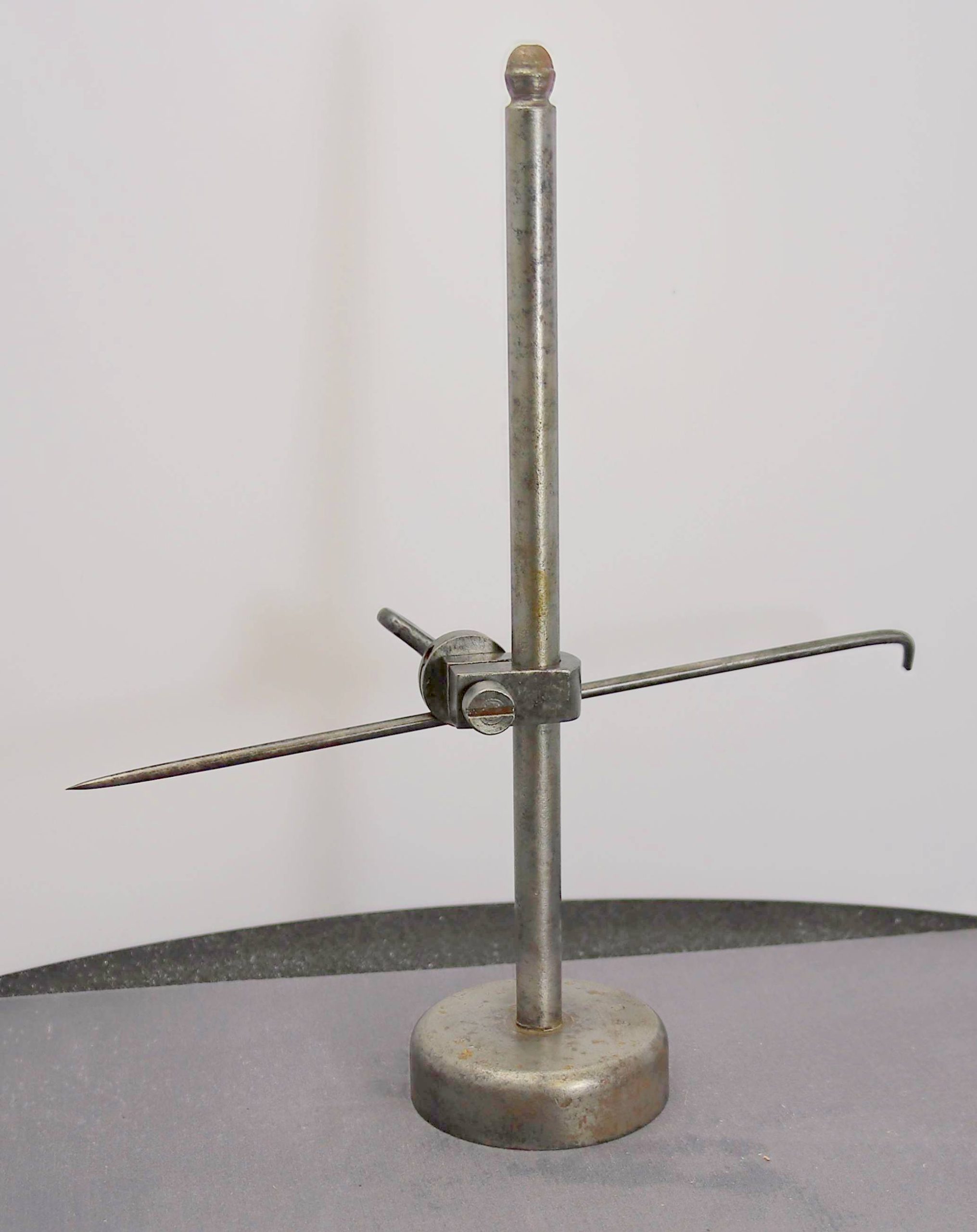
Some time ago Ian Middleditch (@Ian@StEnochs) and I were discussing making globe lubricators and I had made a form tool to turn them when Ian suggested that I use brass ball bearings drilled through instead. So I ordered some in a couple of sizes from China for about £3 or so for 50. At the time I drilled a couple of the smaller ones out, made a pair of lubricators and put the rest away in a drawer. So I thought I would dig them out to see if I could make some blower valves.
First I dug out a few lengths of tube to see if I had any suitable to hold the brass balls for drilling. I had a vague idea that last time I had used a length of copper tube and it seems that my memory served because the only length of copper tube that I had was perfect.
So I popped it in the lathe and used a countersink bit to falr the end slightly before cutting a slit with a piercing saw to allow the chuck jaws to tighten and hold the ball for drilling.
Jig for drilling first hole
Next I did the same at the other end but this time I used a slitting disk to widen the slot that it would accept a 0.9mm rod in the slot (my friend had pre drilled his hole in the smokebox 0.9mm.
Jig for drilling 2nd Hole
Then I drilled the first hole 10 1.2mm deep
Brass ball mounted for drilling first holeDrilling holes in the brass spheres to 1.2mm
Next I soldered in a length of 0.9mm nickel rod
Blower valve with locating stem drilled
Then it went back in the lathe to cross drill at right angles
Valve mounted for drilling 2nd hole at right anglesBlower valve with 2nd hole drilled
Finally some nuts with a hole in one end for the end of the handrail and a setm on the other to go into the brass ball were added to complete the fitting. The photos do show an oval base but this was left off initially to see how it fit height wise with the handrail. a base could be files up from thin shim stock if there is room.
Blower Valves for Stock
As you can see I made one for my friend and a few more for stock while I was set up. last night I had a quiet count up of the ex NER engines in the queue that require them and I think I need another half a dozen. So I will do those this morning while it’s all fresh in my mind.
I bought it along with a number of other hand tools which I have subsequently restored over the last year. But I actually bought the job lot on the basis of it containing this. My idea was to make a lathe Tool Height Setting Gauge from it loosely based on the GH Thomas example which is marketed as a kit by Hemingway Kits.
A fellow parish councillor recently gave me a few pieces of steel one of which was perfect for making the two height setting arms.
Back in June last year (Here) after some discussion on the Guild forum about tapping guides I made one but since then I haven’t had a circumstance where I might actually use it.
Yesterday while doing a little job I needed to tap a 12ba thread in two sides of U shaped pieces. By gripping them (they are rather small and fiddly) in an engineers clamp I was able to rest the guide on the flat side of the clamp and use my shop made tap spinners to tap the holes. One tap spinner holds the taper tap, while the second has the bottom tap.
Set up for tapping small holes in U shaped brackets.
I have been working away on small bits for 8425 and I have now got to the front lockers on the tender. These have a number of hinges which have tiny rivets that need to be pressed out very close together.
I tried my smallest anvil and that didn’t allow tight enough spacing so I made another.
The one on the left is the smallest one that I had made previously and one that I have used a number of times recently. The one on the right is the new one and since the photo was taken I have blackened it and used it successfully to press out the rivets on the locker front
Recently I bought a another job lot of old tools via eBay. I bought them specifically for a scribing block with a round base which I intend to turn into a tool height gauge for my lathe.
In amongst the other tools most of which appear to have been made during an engineers apprenticeship was this.
Something Missing
I had no idea what it was or whether it was complete (I suspected not). It turns out y suspicions were correct and it is a shop made combination universal bevel with one of the bevels missing. Someone who knew what it was point me at a photo and from that photo I have been able to make replacement parts based on the sizes of the original parts.
These are the parts that I made. The thumbnut and the retaining screw were made from a scrap large bolt and the bevel itself was a part of a piece of plate which a friend who repairs heaters on poultry farms gave me from his scrap bin.
Way back in July 2022 I made some additional anvils for my restored Double Leakey Rivet Press which for some reason I never shared.
Laeky Rivet Press additional Anvils
A conversation with fellow Guild Member Michael Holland had me on the anvil trail again. We were discussing my Leakey learning experience while making the recent gun shield for the 18 pounder gun. Michael mentioned that he had turned round anvils for his similar rivet press with specific anvils for each spacing. Still having material from one handle of my recycled die holder, I made a series of anvils for small rivets (0.63mm hole).
Leakey Rivet Press – additional anvils for precise spacing
I also took the opportunity to hot blacken them all. I also intend to make a similar set for slightly bigger rivets (0.8mm hole) which should them allow me to cover most eventualities.
Over on one of the forums that I frequent, it was suggested that I might add rifling to the barrel. Well not quite rifling in the barrel but perhaps equally mad.
From the photos of the real thing I note that the wheels have brass hubs. Nothing unusual there you might think but unlike most hubs etc which have hexagonal collars for tightening with a spanner these have octagonal heads. Now I have a hex collet block and a pin vice which at a pinch cut be brought into service but they would still only have six sides. Again I could have drawn them up and had them 3D printed then painted them with brass paint and job done.
However on one of my favourite machining YouTube channels the guy who does some amazing things uses a “5C Spin Indexer” For those that are not familiar “5C” is a type of collet. I don’t possess any 5C collets, so although I could make use of the functionality of a spin indexer the likelyhood of my buying one was very slim. Then some time ago I discovered that Arc Euro Trade the machinery omany that I bought my mill from stock a 5C spin indexer that has an ER32 collet adapter. Now I don’t have any ER32 collets either but I could see me getting more use from them as they are much more flexible in use than 5C collets. With 5C collets you pretty much have to have a separate collet for every size whereas ER collets usually have approximately 1mm range so a 10mm ER collet would Hold stock from 10mm diameter down to 9mm diameter so you need less collets to cater for a wide range of stock sizes.
Having said all that the 5C/ER32 spin indexers were still getting on for £200 so I couldn’t justify buying one. Then just after Guildex I got a sales email from Arc reducing them to just over £130 so having not spent up at Stafford I took the plunge. I still didn’t have an ER32 collets but my son bought me a set for my birthday.
To get it to mount on my mill table I had to mill a couple of slots to accommodate the width of the T slots but that done I was able to give it a test run yesterday. – The delay in getting to it was working out how I might hold it to actually cut the slots.
That done I gave it a test run on some 3mm brass rod. Unfortunately I hadn’t noticed the hole in the end which precluded me from using it for one of the hubs.
Following my posting of the Joe Pie tap wrench on the Guild forum there was a bit of discussion on the types of tap wrenches in use and one member shared a BA tapping guide that he had bought commercially. Which I thought was a great idea for tapping holes that are too inconvenient to fit in a vice
Having been given the idea, I couldn’t resist having a go at making one this morning.
BA Tap GuideBA Tap Guide
I even managed to use the reject first attempt at making a drawbar for the Princess which I broke during machining due to me doing the wrong order of operations. I keep one of those square plastic trays that Slaters pack their small items like plunger pick-ups horn guides etc. on my workbench and all my small offcuts of brass and nickel go into it. Once I had machined each end off it was perfect for the guide bush.
I probably over engineered it in so much as I turned the end of the bush down to 5mm for 1.6mm and drilled a 5mm hole in the flat bar which is 1.6mm thick. It was a nice tight fit but I realised that due to the bar being drawn, it wasn’t exactly flat on top and the guide sat at a slight angle. still having the coordinates in the mill from drilling the hole I used a 6mm end mill to mill a recessed flat to accommodate the bush. I checked for squareness with a 1-2-3 block and then soldered the bush in.
The hole in the bush is 3.3mm and will take my 6 -12ba taps freely but with virtually no sideplay. I also have a 14ba tap and I might at some point add another guide bush at the other end of the ‘handle’ with a smaller hole to take that.
I mentally kicked myself up the backside and got the sand pipes installed a couple of days ago so yesterday I took a break and made up another couple of Joe Pie inspired tools, which he shows in use in one of his videos.
These were an additional tap spinner which has an aluminium knurled grip but a steel inner so it shouldn’t wear with use. I also made a depth stop to fit over the tap if I wish to only tap a hole to a specific depth.
Miniature Tap depth Stop
The two fit together as above, or you can use them independently as below.
Miniature Tap depth Stop
In the video, Joe showed that he made his in pairs. This is so that he could have a taper tap in one and a bottom tap in the other. Having made the initial example, I still had a bit of material left so I decided to see if I could make a combined tap spinner and depth stop.
Miniature Tap depth Stop
It turns out I could, in the image below you can see the steel core inside the aluminium grip.
Miniature Tap depth StopMiniature Tap depth StopMiniature Tap depth StopsRemains of Die holder after using one handle and part of the casting
Just in case you are wonder what I used to make them I used the remains of one of the handles on the scarp die holder. I put it in the lathe and carefully parted the aluminium where I thought the steel roughly ended (as it happens I could have gone a little further) then having noted how securely the aluminium was attached to the steel core I realised that I could turn the remains of the casting attached to the bar into a round usable piece to make something from and the idea was born. I also have the other side to do something similar from. I can see more tools for even finer taps in the future. Unless I think of another tool to make instead.
Those who joined me for my Gauge O Guild an Evening With Session will have heard me mention YouTuber Joe Pie as someone whom I have learned a lot of techniques and in the past I have made a couple of his shop project tools
Needing a distraction from my current endeavour which has been quite frustrating I decided to follow this video and make another small tap handle. I have previously made one similar to the one that he shows at the start of the video but I made the hole in it a bit big so it’s more suited to larger shanked taps.
As regular viewers of my posts will know I am a great believer in recycling and early this year I bought a job lot of vintage tools from eBay for the princely sum of £7.50 I really bought them for the 3MT-2MT sleeve that was included but there was also a very well made large tap wrench a Moore and wright imperial ruler, a set of sprung external calipers and a couple of 1″ die holders. Of the latter one was very well made and as I have a couple of 1″ dies will come in very useful. The second was a bit battered and had an aluminium casting for the die holder with a couple of 1/2″ steel bars as the handles. This I consigned to the useful bits box and so part of one of the handles became my material for making the miniature tap handle.
Recycled Die Holder
I popped the whole thing in the lathe and being very careful of the large lump in the middle I parted of approx 65mm (just over 2.5″) this allowed a little to tidy each end up bringing it back to a finished size of 62mm or a whisker under 2.5″ .
Then I followed Joe’s steps. I adjusted my hole dimensions to suit an M6 cap head screw so I drilled 5mm for the tapping size, 6.5mm clearance and then 10mm to recess the head of the screw. I drilled until the head was just proud of the end of the handle and then used a 10mm end mill to flatten the bottom of the hole and allow the screw to just sit inside the handle when fully screwed home.
Miniature Tap WrenchMiniature Tap WrenchMiniature Tap Wrench – 12BA Tap
I drilled a 4mm hole in the centre which will take up to a 4BA tap (It might take bigger but that’s the one that I measured as I mostly use smaller than that). Shown here with a 12 Ba tap inserted.
Miniature Tap Wrench
Lastly I heated it up and dropped it into some olive oil overnight to give it a nicely blued appearance – Although I had cleaned it with IPA I went back and did a small adjustment from which I didn’t clean the oil inside out again before the heating. Although I couldn’t see it, this must have created a bit of smoke, which set the workshop smoke alarm off. At least I know that it works.
This seems to be the only shot that I have of the X axis scale in place with it’s chip cover.
Then I mounted the display – you will note that the bottom Z Axis display is reading al zeros this is because at this point I was still awaiting the longer replacement scale.
There are quite a few options for mounting the display you can angle the bracket out from the side of the mill if you have somewhere to mount it. I chose to fix it to the bench alongside.
Then it was onto fitting the Z axis scale. This was reasonably straightforward in that I was able to fasten the scale itself directly to the rear of the column. I confess that I did initially get it slightly too low which reduced the amount that I could raise the head of the mill. Meaning that I had to redrill one of the holes higher up to get maximum height.
I was also able to finally use some of the brackets and mounting plates that came with the scales again fitting to the yoke which raises the head was reasonably straightforward.
What did find was that I had to turn some spacers from aluminium bar to get the alignment between the read head and the yoke so that it ran up and down smoothly without rubbing on the chip cover.
In conclusion, I am really happy with the DRO and now feel confident to do something similar on my lathe at some point. I do agree with Nick Baines comment that having that level of accuracy does tend to get you a little hung up on hitting 0.005 of a millimetre…
Not feeling at my best since the bank holiday I have let this thread slip a little.
So where were we?
The only possible mounting for the read head on the X axis is the end of the Y axis table. To do this I employed a couple more offcuts of aluminium angle these slightly deeper in section than that used on the Y axis read head.
The brackets needed to fit around the Y axis lead screw so needed a bit of shaping
It did take a couple of tries to get a range of adjustment available in all the different elements of the Z shaped final mounting.
Having got this far with the mill assembled I couldn’t put off taking the mill to bits any longer to drill the end of the Y axis table.
The X axis was a bit more involved in that it was harder to get access to even with the mill unbolted from the bench.
First job I found that the slots in the mounting plate were a bit tight for the M5 screws so I opened the slots with the mill.
I also milled the second slot to have vertical as well as horizontal movement as it’s important to have the scales both level horizontally and parallel to the travel of the table for the highest accuracy. As they come one slot is vertical and the other horizontal but being aluminium they are easy to modify with the mill.
After bluing up the rear face of the table I was lucky in that I had recently bought a couple basic C clamps to use for clamping one of my vices and my rivet press temporarily to the workbench when I need to. These fit quite nicely edge on in the T slot so I was able to clamp the mounting plate in position allowing me to move the table to either side of the column so that I could mark it up without removing the table at this stage.
Again, it was a bit of a squeeze but I was able to drill and tap the table without removing it.
The next task was working out how best to mount the reader but I will cover that in another post.
The next step was working out where to position the reader to get the full length of travel from it. I measured how much space the X axis scale would take up when fitted, added a couple of millimetres for clearance and used that as my forward limit. I then marked the base and drilled and tapped the base.
This is the Y axis scale fitted with it’s swarf cover and working.
There was a convenient ledge on the side of the bed casting which allowed me to add a parallel to get the backing plate up to the right height to mark for drilling the mounting holes. The 123 block is just holding it in position.
I added some engineers blue and marked the holes with a scriber then punched the centre.
Drilled, tapped and cleaned up with IPA
The backing plate in place, so far so good.
A trial fit of the scale to work out where the reader needs to be fastened to.
At this point I realised that I would need some packing pieces behind the mounting plate to make it stand off due to the useful ledge that I referred to earlier and allow the reader a clear track without being forced to run at an angle and to allow the fitting of the chip shield which didn’t quite fit when flush against the table.
I used a slitting saw to cut down some sheet material which some bar stock had been attached to to stop it being bent in the post. It’s quite interesting material in that it is two layers of thin aluminium bonded either side of some plastic material. Being layered it’s remarkably strong and light and I thought it too good to throw away so it went into my useful bits box.
You can just make out in this shot where I slotted the vertical mounting holes in the angle bracket, again to allow the reader to track without adding undue pressure. You can also see the packing strip between the mounting plate and the edge of the table.
The Warco items duly arrived and each scale, came with a main rear mounting bracket and a pair of additional mounting brackets (Shown below) and a selection of M4 and M5 cap screws.
Main mounting bracket.
Warco Glass Scales Mounting Brackets
These are the additional brackets that were spare as I only ended up using one of each along with some sections of aluminium angle which I had rescued from a set of shelves that I had dismantled.
To ensure that the job wasn’t stopped for lack of drill bits if I broke any, I put in and order to Drill Services Horley for a couple of 3.2mm and 4mm drill bits. Of course because I had them to hand I didn’t break a single drill bit.
All the holes drilled in the mill itself were done using a battery hand drill and being cast iron it was quite easy going if a bit messy.
The main mounting bracket holds the glass scale and then the read head is mounted so that when either the read head or the scale moves it reads off the distances. In my installation I have the scales mounted to the moving table axis and the read head’s fixed to the machine bed. On the Z axis this is reversed and the scale is fixed to the column of the machine and the read head moves up and down with the milling head.
I decided to start with the Y axis as being one of the shorter ones so easier to handle and definitely the easiest to access on the left side of the machine. However as soon as I took the 100mm scale out of the packaging I knew that I had made a mistake in getting a second 100mm scale for the Z axis although it would be fine if I was working with the vice or rotary table mounted on the bed it wouldn’t allow the head to come down far enough to mill anything directly mounted to the T slots of the table.
I immediately contacted Warco and explained my error and asked that since I hadn’t opened the second scale, would it be possible to return it, and swap it for a 200mm scale. They were happy to do so and would sort out any additional cost incurred once they had it back with them. I returned it to the address on the signature of the person who had sent the invoice. This proved to be a mistake as it turned out that they had moved from that address so the package was returned to me. I called them and advised that there would be a delay due to my sending it to the wrong address which was on their email.
I looked at the actual invoice and noted their new correct address and re sent it there. As good as their word they very quickly despatched the replacement and didn’t charge me a penny which despite my frustration at them not having the correct address on their correspondence I did appreciate.
For my birthday last October I received a Digital ReadOut (DRO) kit for my Sieg SX1 LP mini mill. I fitted it over a weekend last October and although I took photos as I did each stage, I haven’t yet got around to writing it up. Paul’s posts (@OzzyO) on fitting a DRO to his mill prompted me to get my finger out so that anyone who is interested will get a couple of takes on fitting them to different types of mill.
As I am not anywhere in the same league as Paul when it comes to machining, my first port of call when looking was to YouTube. To see if anyone had done a video on fitting a DRO to a similar mini mill. I was quite surprised that at that time there wasn’t any to be found (there may well be now as I haven’t looked since).
Having realised that I was essentially on my own, my first port of call was to ring Arc Euro Trade whom I bought the mill from. To ask if they did a DRO kit for my mill. I was a little surprised that they didn’t, as they seem to cater well with other accessories and tooling for the range of machines that they sell. Their recommendation was to talk to a company called Touch DRO who apparently do something suitable.
I have seen a few videos which featured Touch DRO units and confess that I was not keen on the idea. This is on the basis that they require the use of scales, which connect via Bluetooth to a tablet for the display. I spent 20 years in IT support and the last thing I want is yet another device.
Again on the basis of seeing a few videos on badged variants of the units supplied by Warco I opted to buy from them. I got a display reader, two x 100mm glass scales and one x 250mm.
The idea was that I would use one of the 100mm scales on the Y axis (front to back movement of the table for those unfamiliar with the axis terms) and the other for the Z axis which is the up and down movement of the mill head. This latter proved to be a mistake which I will elaborate upon later. The 250mm scale was to be used on the longer X axis table (which is what the LP designation of the model number refers to).
Although I have a Moore and Wright depth micrometre, I recently needed o check the depth of a hole that I was drilling which was much smaller than the rods on the depth mic.
I had seen a video on YouTube where a gent in the US made a simple depth gauge from a length of aluminium bar stock , a thumb screw and a length of rod.
As luck would have it I recently bought some 2mm silver steel rod for use as retaining pins for gearboxes I also had a piece of 10mm x 100mm x 14mm rough cut piece of mild steel which was left over from my lathe upgrades. The rough cut edge was actually along it’s length rather than one end (although the ends were not perfect either.
Due to the need to mill down the stock to square up the rough cut edge I thought it worth trying my hand at milling some angles along what would become the top of the gauge.
Sadly when I came to drill out the hole for the measuring rod the 1.9mm drill wandered of line and the hole although square front to back was a little off to one side. Although it was not out enough to stop it being functional it bugged me so in the end I mounted the body in a 4 jaw chuck in the lathe and used a 4mm diameter end mill to open out the hole and square it up. The end mill wasn’t quite long enough. so I had to run a drill through the last millimetre, but by then the hole was square and the problem was solved.
Finally I turned a nickel silver bush to fit the hole and them drilled that out 1.9mm and reamed it to 2mm for the measuring rod.. A turned brass thumbscrew completed the job.
The flutes on the head of the thumbscrew were machined using my Proxxon dividing head on the mill table. I made a second smaller thumb screw for the end of the measuring rod so that it didn’t poke my in the eye in use. Lastly I blackened the body of the gauge using Birchwood Casey Gun Blue
When making my mini tap holders some time ago, there was a discussion about making, versus buying tools over on Western thunder, where I mentioned that I could buy one from Arc for under £10. I duly bought said tap follower from Arc Euro Trade and what a journey that turned out to be. When it came the grub screw in the image fitted into the back of the tap follower to retain the spring.
Modifications To Arc Euro Tap FollowerModifications To Arc Euro Tap Follower
Which in itself was fine aside from the fact that the body of the tap follower was too big to fit in either of my Jacobs chucks and although I could have swapped the chuck out for a collet chuck that would have been a lot of messing about each time I wanted to use the tap follower. My solution was to turn up a threaded pin to replace the grub screw. Which on the face of it is simple, except I couldn’t determine what thread* was in the tap follower as supplied, so I ended up re-tapping it to M10.
Modifications To Arc Euro Tap Follower
That done I gave it a whirl and found that the hole in the body is far too big with too much slop for the guide rods to actually hold the tap straight. Which of course is the whole point of the exercise…
Hopefully you can just make out the gap between the two in the close up below. What should be a close sliding fit is far from it.
Modifications To Arc Euro Tap Follower
As I had already modified it I couldn’t really return it to Arc Euro so I put it in a drawer in disgust and moved on.
Fast forward to a couple of days ago and I had need to tap another hole in the lathe and I just happened to have the length of 8mm stainless rod (which I use for tightening my collet chuck) in my hand when I saw the tap follower in the drawer. I took it out and quickly dismantled it and tested the 8mm rod inside the body of the tap follower. It was a perfect fit. I cut another length from the piece I have in stock, to suite a new double ended guide rod and then turned each end down to a close sliding fit. One end has a point, the other has a 60 degree countersink to accommodate taps with points on the end.
Modifications To Arc Euro Tap FollowerModifications To Arc Euro Tap Follower
Now I have a tool that does what it was supposed to when I bought it. I cannot blame Arc for the initial problem of the shank not fitting my drill chucks because it does state the shank size on their website but I missed taking note of it.
The poorly fitting guide rods is another matter.
You live and learn and I suspect that in this instance I would have been better making my own tool or buying a better quality example in the first place. At least I have been able to remedy it and I may at some point make up a second shorter version to utilise the spare guide rods.
*Having checked the Arc Euro Trade site as I was typing this to confirm that they do indeed note the shank size, I also noted that all the other measurements although primarily stated in millimetres, are in fact conversions of imperial sizes.
As I don’t possess any imperial taps or dies I was doomed from the start in working out what size the thread might be.