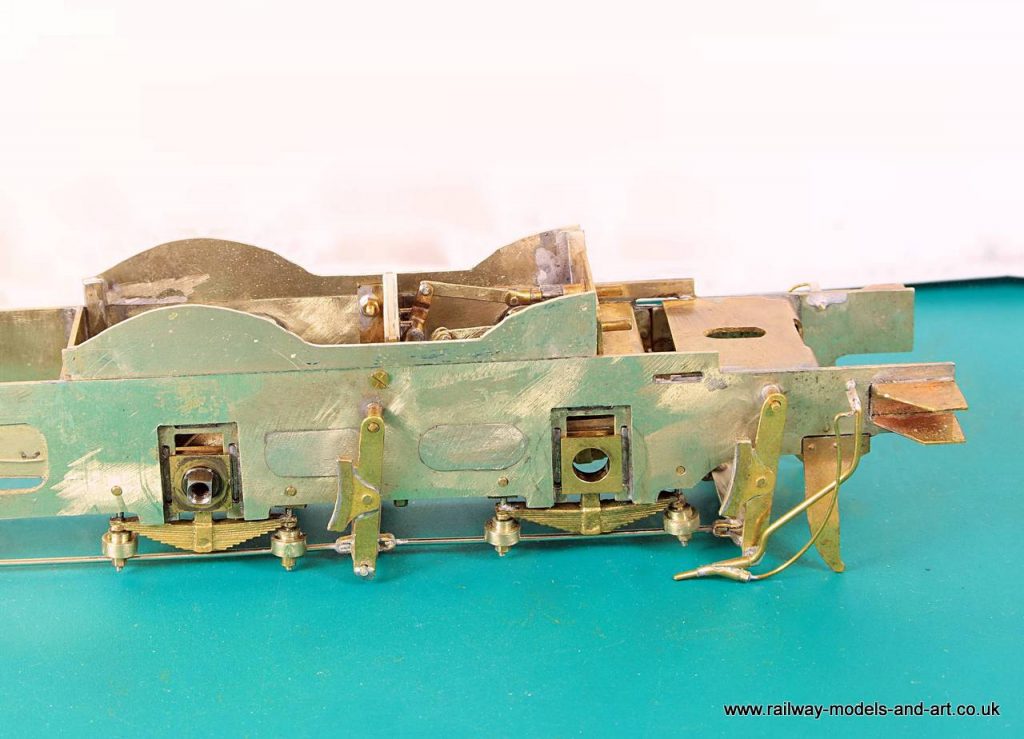
David Andrews Princess Royal – Cylinders assembled

Back to the Princess this week after moving the J6 along.

In the end I decided to take a bit more of the edges of the cylinders and then I fitted the covers. Before I did that I soldered the slide bars in place as I didn’t want the heat from soldering them in place to spring the cylinder covers loose. As it happens I had to adjust one of the slide bars as I hadn’t got it quite square and the cylinder covers are such a good fit that although the solder softened, they never moved. Something to aim for on future builds.

David Andrews Princess – Cylinder covers and slidebars fitted

After fitting the slidebars I mated them up with the motion bracket and realised that once I join the two together them crossheads become captive so I need to do work on the motion next to ensure that all is well before I solder the slide bars to the motion bracket.

The first hiccup is a result of using extras to the kit. I used the David Andrews Slide bars and crossheads for the simulated inside motion because they don’t have as much details as the LG Miniatures versions. Now I come to fit the LG crossheads with the connecting rods which are replacements from Premier Components I find that the LG crossheads are different to those that I have used on other builds in so much as they have a slot in them rather than an open back. This means that I will have to mill the connecting rod ends to get them to fit in the slot.

LG Miniatures Cross head with Premier Connecting Rod

A picture paints a thousand words as they say…

Gladiator J6 Final Chassis details

A couple of weekends ago I was demonstrating Loco building at the Stainmore Railway Model Railway show. I took along the chassis for the J6 and had it running on the rolling road all weekend. Besides giving the motion a really good bed in it attracted a lot of attention.

So much so that I plan to make up another chassis with inside motion for my demo stand.

On the back of a great weekend out I decided to see if I could crack the construction elements of the J6 last week.
The remaining jobs were.

Fit glazing
Add Milliput to the back of the balance weights to make them solid rather than just an etched front.
Fit the sand pipes
Fit the remaining linkages between the brake pull rods and the brake cylinders
Fit some Frame extensions under the boiler between the front pairs of wheels to hide the rear of the wheels – following Tony Geary’s lead.

Gladiator J6 Balance Weights


Balance weights, I added a coat of primer to bled it all in before final paint and weathering.

Brake cylinder cranks


The first bit of the brake linkages

Gladiator J6 Sandpipes and false frame tops


Front sandpipes and Frame extensions. Before fully soldering them in I tested the frame extensions at one side by tacking them in and the seemed perfect. But the chassis mustn’t have sat down properly because I noted while testing for clearance on the rear sandpipes that they need trimming down a bit.

Gladiator J6 Rear Sand Pipes fitted


Rear sandpipes. I had to fit the tops of them very close to the frames to avoid the injector pipework but I got there after two or three adjustments.

Gladiator J6 Rear Sandpipes and brakes linkages


Last but not least a couple of shot of the remaining brake linkages. Although soldered at the rear the ends of the rods are a loose fit in the turnbuckles so allowing removal of the brakes.

Homemade Nut Spinner Handles

While doing a recent loco repair for a fellow Guild Member, I found that I was constantly swapping the head of my Markits nut spinner between 8BA and 12BA with the result that quite a few times it was the head of the nut spinner that unscrewed not the nut as I hadn’t tightened it enough. I use the 8, 10 and 12BA heads most frequently and rarely use the 14BA and 16BA heads. Thinking about it, I don’t think that I have ever used the 6BA head so far although I do have some 6BA hardware so I probably will at some point.

For those unfamiliar with what I am talking about this is the ‘Markits’ version

Markits Nut Spinner

I decided to make some spare handles so that I could have the 8, 10 and 12BA heads on individual handles and then fit the 14BA and 16BA to a double ended handle and second double handle for the 6BA and any other size that I might come up with at some point. In the meantime I will make a rounded end insert just to finish it off.

Homemade Nut Spinner Handles

I suspect that Markits use 10mm hex bar to make theirs. I did mine the longer way using 10mm round and then milling flats on them. Of course I had no sooner cut them all and drilled for the thread when I found a length of 10mm brass hex but isn’t that always the way.

If anyone wishes to do something similar with theirs, the thread on the Markits heads is M5 x 0.8

Restoration of a Double Leakey Rivet Press Part II

A bit of online research found me a photo of what it should look like so I set about cleaning it up. It turns out the handle was on upside down.

By good fortune I had a couple of pieces of rod in my stores that would make a replacement for the depth guide. I had a choice of Nickel Silver or Silver steel so I chose the latter. as being more suited to a machine.
I turned a 60 degree point on it as looking about right from the photo and then milled a flat for the work piece to rest against.

Next I went over it with a wire brush in my Dremel and I was pleasantly surprised when most of the surface rust came off leaving the painted surface underneath. I quite like the lived in look so I am not going to repaint it as I had originally planned. all that remains is for m to fasten it to a suitable piece of wood and hopefully to make some addition anvils for it.

Double Leakey Rivet Press Part II

In my searches I determined that as bought they came with 4 anvils whereas mine only has one at the minute. The good news is that a member of Western Thunder has one of these so I have asked if he will take photos of the additional anvils and get me some key dimensions and I will have a go at making some more. I recently scrapped a duff Compound Mitre saw that I had, had for 20 years. Before scrapping it, I recovered lots of useful bits of steel and aluminium. One of the former should be just right to make the anvils.

Restoration of a Double Leakey Rivet Press

After collecting a couple of pre orders from Finney7 and Metalsmith and then buying other bits and pieces including some driving wheels for a J21 (I already have tender wheels for it. I risked a look on the Bring and Buy stand. I went later because I didn’t want to be tempted by a too good to miss kit as I have far too many as it is. What I did find for the princely sum of £19 was a Double Leaky Rivet press. I was amazed that it hadn’t been snapped up and I wasn’t the only one, as when I was paying for it the gut who served said that he thought that as he was putting the price label on he thought that someone would be taking it out of his hands.

It needs a little TLC and at first glance I knew it was missing the depth guide but otherwise pretty good condition for something that will be getting on for 30 or more years old.

This thread is to share the journey of it’s restoration.

Double Leakey Rivet Press

David Andrews Princess Royal – Removable Eccentrics

Following a question about parts for the inside motion on the Guild forum, a fellow member posted how he had achieved a similar result to what I am working on but without the use of a lathe. I must off thanks to Harold because his post gave me the solution to one problem that I had been pondering (how to space them apart for soldering) and for prompting me to think that I didn’t actually need to solder them to the axle at all. I could solder them to the bush which acts as a spacer and would allow a hole to be drilled to make use of the taper pin that holds the axle together.

David Andrews Princess Royal – spacer-retaining bush
David Andrews Princess Royal – Removable eccentrics

In true Blue Peter style, here’s two I made last night before I got my head into gear and correctly worked out the width. They will go in the spares box as I am sure that they will come in for something.

Some I made earlier!

David Andrews Princess Royal – Inside motion update

Today I made up some connecting rods for the inside motion. They came from the scrap etch box and were originally for a Black 5. I cut off the big end bosses from all the pieces and then soldered them together in pairs. Once I had measured the length, I cut them to final size and grafted some Laurie Griffin eccentric straps onto them. I have calculated that the home turned eccentrics will give about 3mm of travel fore and aft but that will be sufficient to give the sense of movement though the holes in the frames.

David Andrews Princess Royal Inside Motion

Gladiator J6 – a Milestone Reached, the inside motion, wiggles

A bit of a milestone was reached in the Pulham household last night. I have been tinkering for a number of days with the inside motion, getting it all to fit in the frames. I had to mill the inner side of each crosshead to clear the eccentric straps etc. so they are now handed and I also had to enlarge the centre section of the motion bracket to allow the assembled eccentric rods, expansion links etc to pass through it. Then came the final job of determining the length of the connecting rods and cutting them to length.

Once they were cut and tried in place the length was right but they wouldn’t fully rotate because I hadn’t made the slots in the motion bracket deep enough. Much filing and testing ensued but I didn’t seem to be getting anywhere and then I realised that because of the constant assembly/disassembly for testing, I had the frames upside down. What I was viewing as the top was in fact the bottom so I had been adjusting the wrong side. More filing and test ensued and I got there in the end.

Having tested the pistons successfully with the valve parts resting outside the motion bracket I put it all together inside for a further test.