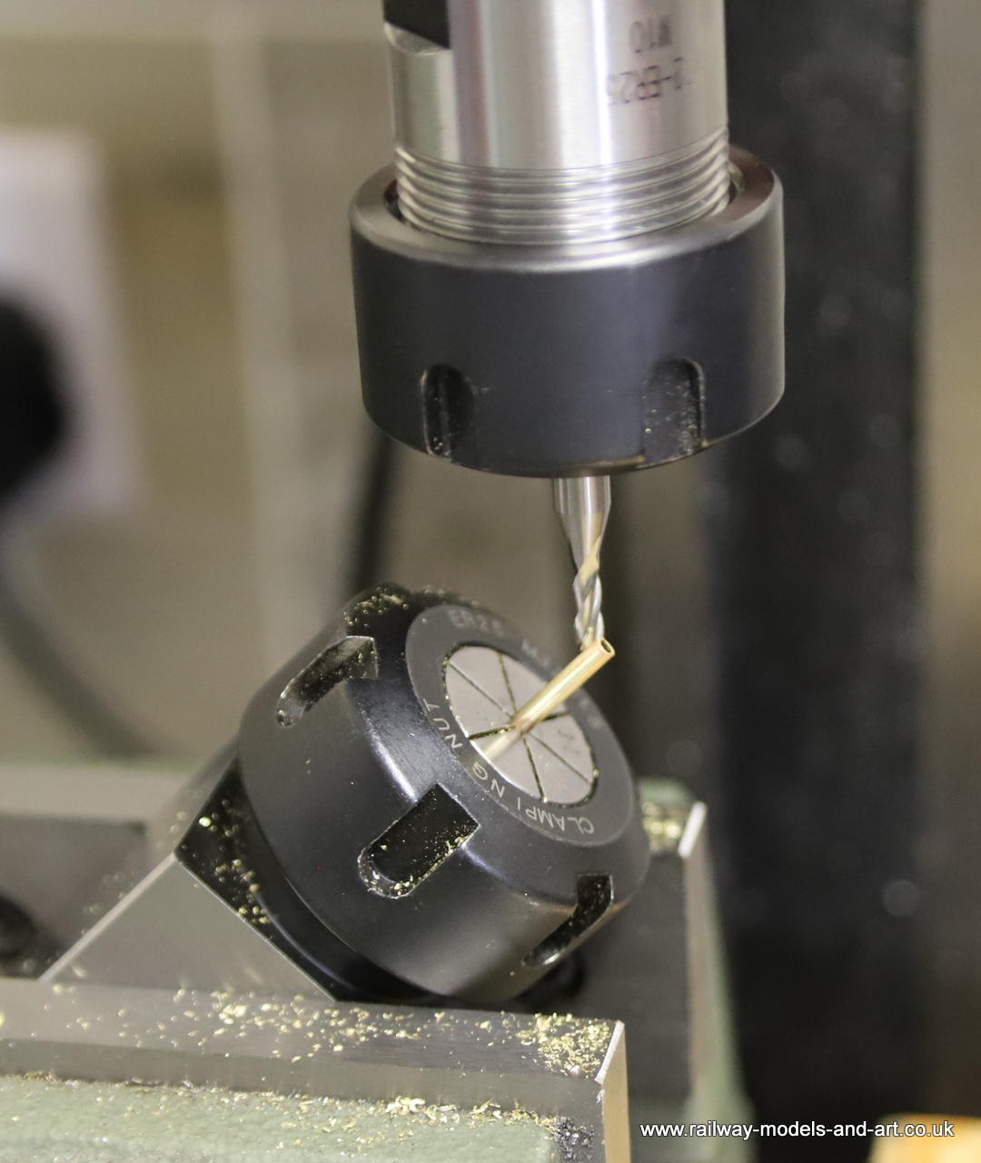
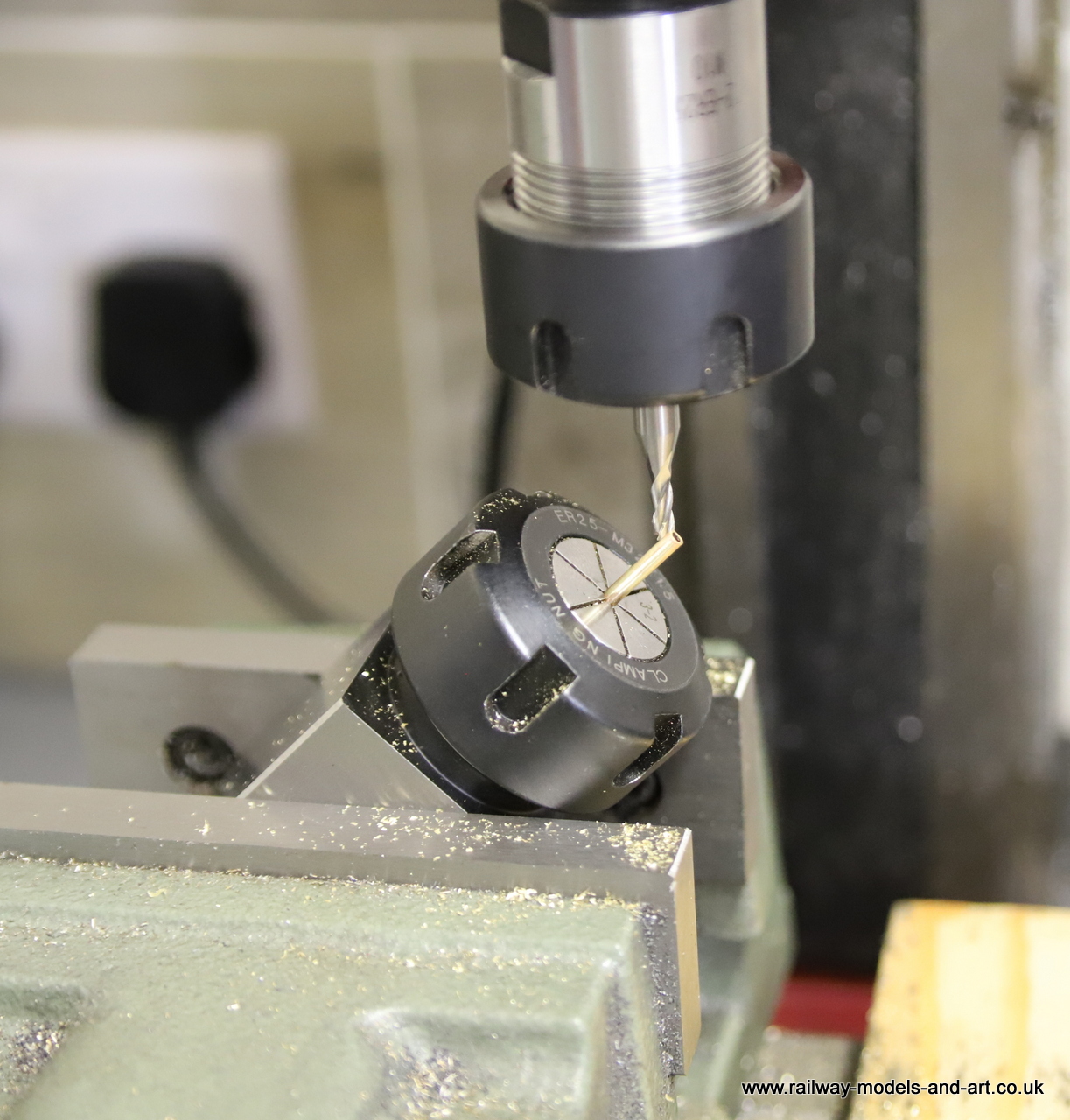
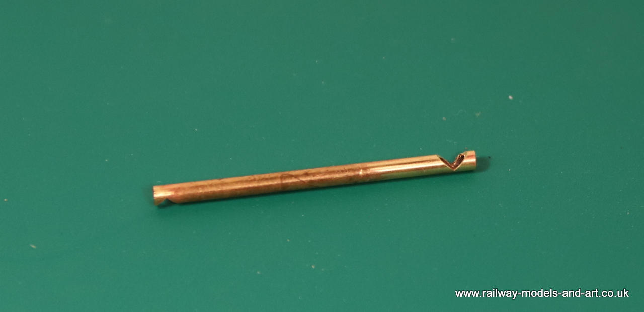
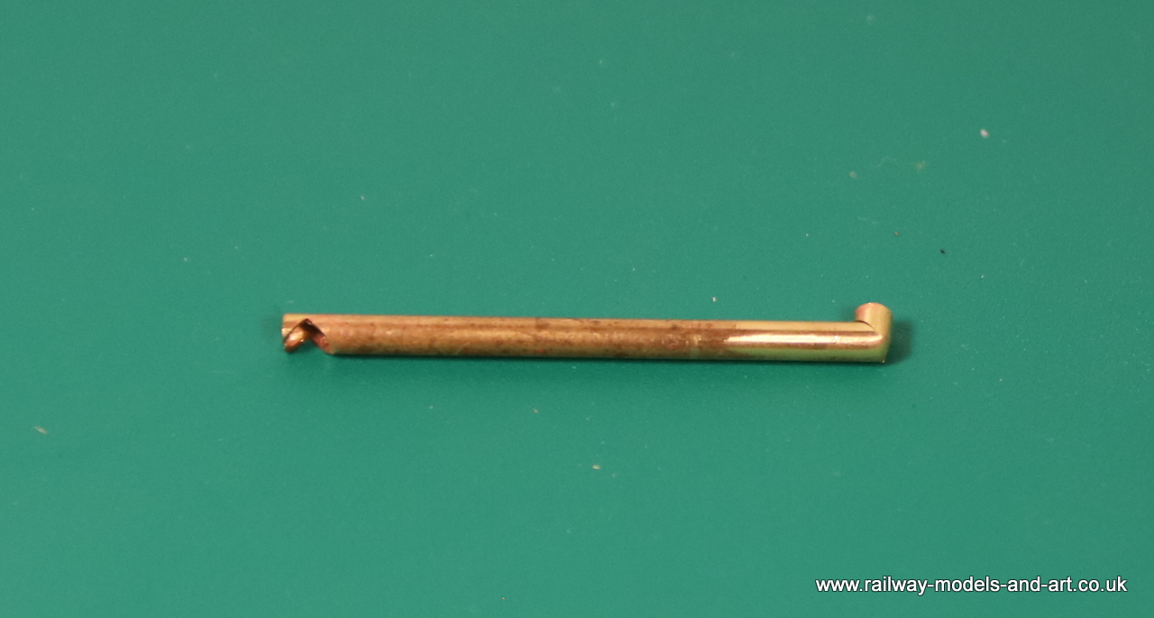
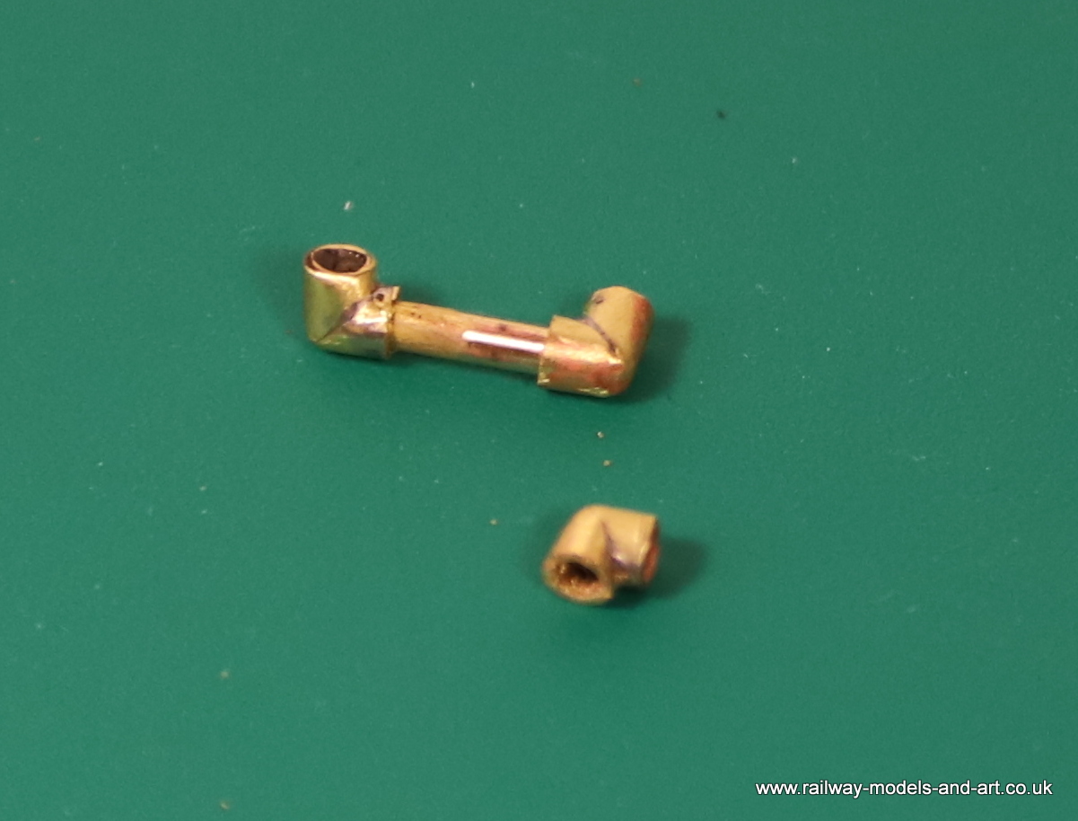
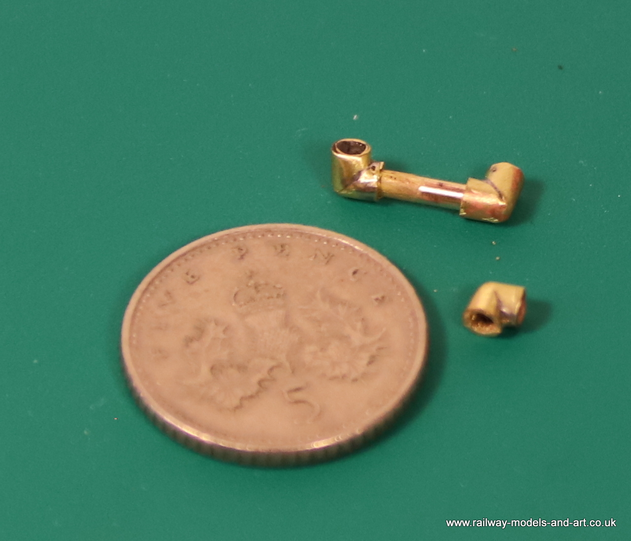
When posting the above about making up the vacuum pipe, I completely forgot to mention the making of the pipe elbows. In the past I have used a square file to file a V groove in some tube and then created the bend. This time I thought that I would have a go at doing it with the mill I set a collet block at 45 degrees using a set square and then used a 3mm end mill to cut the slot.
Milling a V cut out for a right angle bendMilling a V cut out for a right angle bendV cut out for a right angle bendright angle pipe bendRight angle Pipe bendsRight angle Pipe bends
Although I still need to finish of the chassis, the body and tender are pretty much complete, so I took the opportunity to return to this build and pipe up the injectors, and fit the vacuum pipe down the right hand side valence.
I had drilled the holes for the pipes and cut lengths of copper wire some time ago, then they were put aside.
Injector castings piped upInjector castings Pipes bent to shape and cut to lengthInjector castings Pipes bent to shape and cut to lengthInjector castings Pipes bent to shape and cut to length
The vacuum pipe was surprisingly difficult to photograph with it being so long.
I was most surprised to receive a message from Paul Moore this morning to say that he had ended up painting the B16-1 that I built back in 2017 and would I like some photos of the finished model.
I jumped at the offer and here are the photos copyright of the lovely job that Paul has made of the paint job
Photos copyright of Paul Moore and posted with his kind permission.
Although I dressed the backhead a couple of weeks or so ago, I hadn’t managed to get it to fit into the cab before now because the stub of the whistle protruding through the cab roof stopped it from sliding in. One of those little few minute jobs that seem to take forever to get around to…. I finally got to it and the backhead now fits in place as if it was made for it.
Gladiator J6 Backhead fitted in the cabGladiator J6 Backhead fitted in the cabGladiator J6 Backhead fitted in the cab
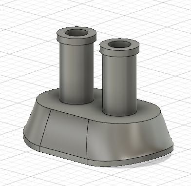
After spending a week teaching myself 3D drawing, I was back
at the workbench today. I had originally planned to just turn a couple of
appropriately sized top hat bushes, file some flats on them where they come together
and job done. My recently acquired mill offered more possibilities to make
something that at least looks like the original even if it doesn’t attach in
the same way. This will be soldered to the cylinder front in between the slide
bars, instead of being suspended from a substantial bracket between the frames.
This is my first real item produced with the mill and I am
happy with how it turned out.
Milled Expansion link support bracketMilled Expansion link support bracketMilled Expansion link support bracketMilled Expansion link support bracket
This is where it will sit in between the slide bars on the cylinder front. I have added some fastenings to make it look as if it should be there, when it’s ultimately lost in the gloom between the frames.
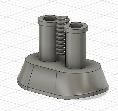
This is the final version. it was a bit of a challenge to get all the lever elements constrained so that I could extrude it but I got there in the end.
By turning different elements off as in the photo I can create separate STL files for just the lever, the complete valves without the cover or complete with the cover.
Yesterday saw more progress on the motion for the J6, with the valves almost complete.
I still have the arms to make that connect the valve rockers with the expansion link etc. But I am pleased that I have got this far as I had hit a bit of a mental brick wall with concern that attempts at soldering on the valve rocker supports would result in them dissolving into individual parts again.
As happens often when procrastinating, I worried for nothing.
While I am distracted with outside jobs during the good
weather, I have been working on another of the key outstanding jobs that is
simple to pick up and put down. The back head/plate, is as I mentioned earlier
in the build, a GNR Boiler Back Plate set from LG Miniatures. It wasn’t quite
deep enough so I added a strip of thick brass along the bottom. Also missing
from the set as delivered, were the injectors. Laurie includes a layout drawing
in the set and it showed the missing injectors. An enquiry to Laurie had an apology
and a pair of injectors in the post.
I am not sure if they were from the GNR set or another more
generic pair but a little bit of scratch building had them looking the part. I
had to fabricate one of the levers for the right hand injector from a .9mm rod
with one end squashed and drilled out for the pin and then tapered with a file
in the mini drill (too small to old securely in the lathe).
In the end I only used one of the hand wheels from the set
because they came with cast stems on them and I wanted to fit them to the stem
already present on the castings so I used some cast hand wheels from the spares
box which had holes in the centres. Had I not had them to hand I would have cut
the stems of the castings and drilled them for the ones with the cast stems but
it would have been a bit tedious.
J6 BackheadJ6 Backhead
The GA showed some kind of inline valve down the right hand
side of the cab at the side of the back plate so I knocked one up from a couple
of bits of tube and a cast handwheel from the set.
J6 backhead – scratchbuilt inline valve
My apologies for the greenish tinge it’s reflections from
the green storage box that I propped it against for the photos.
Modelling time this last week has seen me back on the J6. I
have been making progress with the inside motion starting with soldering the
front of the slide bars to the cylinder front and then removing the motion
bracket and moving it backwards to match the drawing in order that it would then
clear the front horn guides.
Motion bracket and cylinder front joined together with the slide bars
Getting them square to each other was a little challenging
so I cut a couple of rectangles of 10thou sheet to set both the distance
between the cylinder front and the rear of the motion bracket and keep them
square at the same time. I used a couple of aluminium hair grips to hold them
in place while I soldered the ends of the slide bars to the motion bracket.
I still need to plot out and drill holes for the support
rods for the expansion links in the cylinder front.
I still need to plot out and drill the cylinder front for the support rods.
I have temporarily assembled most of the motion but I still
need to add the parts to the motion bracket which support and operate the valves.
Motion parts temporarily assembledMotion parts temporarily assembled
Having extended the clearance between the cylinder front and
the motion bracket so that the cylinder front sits in front of the horn guides,
I found that the slide bars still fouled the horn guides. T next task was to
reduce the depth of the front horn block in the lathe so my four-jaw chuck got
a turn. Because I only wanted to effectively face them off. I cheated a little
and fitted a short length of 3/16” silver steel into the tailstock, slipped a
bearing on and used that to quickly centre the four jaw.
Front Hornblocks reduced in depth on the lathe
The next task is to remove a section of the horn guides to clear
the slide bars.
Hornguides now need reducing to suit.
As soon as funds allow, I plan to buy a mill to compliment
the lathe and boy would a mill make this task easier. I can see now why Nick
plans his inside motion fitting as he builds the frames. A lesson learned for
the future! Onwards and upwards as they say.
A fellow modeller asked if I would make him some steps to replace some that were missing in a DJH/Piercy J27 kit that he had bought.
My guillotine and some offcuts of brass sheet made fairly short work of making them. In fact the longest time came from working out how big the parts needed to be. Although I had been provided with a section from a drawing it had been photographed rather than scanned so it wasn’t square on enough to be certain that measurements could be scaled exactly from it. What it did allow was confirmation that taking sizes from the steps in an NER J21 kit was as near as I was going to get.
One of the few remaining details to add to the body are the injectors which sit under the footplate tucked away behind the cab steps. From all the photos that I have of J6’s seeing what they actually look like is a real problem. Then I remembered that I had taken a few photos of the Injectors on the side of the preserved J52 while it lived at Shildon.
While I have a couple of good side views they don’t show the pipes and how they fit.
Then by pure chance I was looking through some photos that I took in the dark hall at York and found that I had indeed taken photos of each end
By cross referencing these with the end that’s visible on some better lit J6 photos I was able to confirm to my satisfaction that these are the same type of injector fitted to the J6 Now all I need to do is work out how to scale them to size – Despite taking quite a few shots at both locations none of them are side on allowing scaling from a known dimension.
Modelling time has been in a bit short supply so far this week but I have managed a few bits and pieces. The key one being, on the back of a delivery of a second set of globe lubricator castings for the J6, I got them fitted. I had to order some more because I have misplaced the first lot but I am sure that they will turn up in due course…
In between adding bits to the GCR Tank, After drilling and pinning the cranks which was thankfully uneventful. I cut out the axle in between the crank webs and refitted the connecting rods. I had to file a little of the sides of one one the connecting rods but very quickly all was rotating smoothly. So much so that I made a short video. Sadly my camera didn’t focus too well on my hands but you get the idea.
Having looked at it for a couple of days I felt that the second runner wagon looked a little bare so I knocked up another toolbox and I added some hardware to them all. It’s starting to come together now. A friend has just sent me some spare ‘Crane Runner’ transfers so I now have enough to do both runners (assuming that I can get them to fit of course.
I am still undecided as to whether to line the counterbalance weight on the crane because the gears on the crane itself will prevent me being able to add any lining around the frame if indeed they were actually lined.
A few tools and lumps of timber and some weathering will bring it all together.
In my quest to clear the
workbench of it’s long time inhabitants I took stock of what was needed to
finish the crane and runner/match wagons. It turned out that to do the bare
bones of the build they only actually needed buffers and couplings. Then I
recalled why the build had stalled. The buffers and couplings that came with
the kit were a bit of a ‘hotch potch’ of different makes/types. I bought it
second hand so I am not sure which of them might have been included originally.
There were a couple of different
type of white metal buffer stocks and a nice set of Slaters cast brass RCH
pattern buffers but there were only three buffer heads. There were buffer
heads/springs and retaining nuts. The trouble was that the springs were
a bit bigger than the normal springs that Slaters and other supply.
I had a look in my spares box
and managed to find three complete sets of Buffer stocks, one set NER, One set
GNR and one set LNER. Which I thought would be typical of a railway company
using whatever wagon was available to use as runner wagons for the crane.
Again, there was a mixture of
couplings so I sorted out three assorted sets and added them.
It was at this point that I asked
for assistance on the LNER forum as to what colour mobile hand cranes would
have been painted by the LNER. I didn’t get a definitive answer but the
suggestion was that they might have been lined black the same as the steam
cranes were.
Armed with this, I masked them
up and painted them black. At this point I thought that the runner wagons were
a bit plain so I made up some toolboxes from coffee stirrers and added them to
what was to become the leading runner wagon.
Engineers TrainEngineers Train
I couldn’t resist posing them with a shabby NBR van and one of the NER brakes to simulate a breakdown train.
Enginneers Train
Still some way to go before I
and happy with them.
To close this particular build off, the Road van is lettered, although I cannot take credit for the fine job on the lettering, it was done by its new owner.
The Road van was painted at the same time as the brake vans but I held off posting photos because they formed part of the GOG virtual show’s lockdown models display. The show was held today so I am not taking anything away from it by adding them to my threads.I enlisted Chris’s help to paint the curved arrows on the plate above the brake hand wheel
D&S NER Bogie Road VanD&S NER Bogie Road Van
Finally I was asked by a friend to take photos of both bogie vans together.
L&Y and NER Bogie VansL&Y and NER Bogie Vans
For those not familiar with it the LMS van is the Dragon Models Lancashire and Yorkshire 30 ton Bogie van now with TaffVale Models.
Today has been a brilliant day on quite a few fronts but the main one being that I successfully soldered the crank axle up without any issues.
I followed advice given to me by fellow modeller Nick Dunhill, which was to use Bakers Fluid as the flux to solder to the steel axle, to replace the piece of steel rod provided to line up the cranks and eccentric with a length of similar diameter brass rod which being more flexible allows the cranks and eccentrics to be squashed tighter together and positioned better. And finally, to wrap wet tissue around the eccentric sheaves to stop the soldered end coming adrift with the heat.
It couldn’t have gone any smoother, I spent some time making sure they were all lined up correctly and orientated against one of the flat edges of the axle end. I grip the other end in a biggish pin vice applied the Bakers fluids from a bulb type dropper and some short lengths of 180 solder curled slightly around the axle either side of the cranks then gently applied heat with the microflame until the solder flashed. While it was cooling I couldn’t resist moving the eccentrics slightly to make sure that they hadn’t become solid.
Next job is clean them up and then before cutting out the section of axle I think that I am going to drill and pin the cranks. I know that Nick doesn’t bother as they aren’t under any real load but I think that I will be belt and braces for this my first go.