This may not be as relevant to some in these days of keyless chucks but here goes.
I have got into the habit of watching Youtube videos on my phone while having coffee, usually on lathes or machining of some sort. During one such video yesterday a guy in the US had made comfort handles for for drill chuck keys and when he explained why it struck a chord.
Today while at the lathe making return crank bushes for the Princess I decided to have a go at a handle for the chuck key for the drill chuck that I use on both my lathe and mill.
Chuck Key HandleChuck Key Handle
Really quick to make and it doesn’t need a lathe to do it. A Drill and a file would suffice. I made it so the handle was a tight interference fit and I did such a good job that I had to drill a 1mm hole in the end to let the compressed air out to allow it to push into the bottom of the main hole in the handle. It got quite a bit of use while making the bushes so this evening and it was so much more comfortable to use that I made a second one for the much smaller chuck key for my Proxxon Mini Pillar Drill
Chuck Key Handle
Both handles are made from offcuts of Delrin rod that I had in stock but they could be made from pretty much anything. I had eyed up wooden dowel, aluminium bar and brass rod before remembering the Delrin.
For those of you not wishing to spend a packet on BA nut spinners from Markits et,al a chance conversation with a friend brough back a memory of a much missed GOG Member whom I have referred to in the past David Smith (known on various forums as DLOS). He was really a model engineer and he had mention in a posting a few years ago that he had made BA nut spinners from appropriately sized caps screws using the hex head as the socket.
Having a spare couple of hours last night I rummaged through my screw box and found that an M4 and M5 cap head screws were just right for 8 and 10 BA and a couple of grub screws suited 12 and 14BA.
Home made Slim Line Nut spinners 8-10-12-14 BA
Although I used the lathe they could be made by anyone with the ability to drill and tap metric threads. I did turn down the heads of the cap screws but again nothing that couldn’t be achieved by putting it in a drill chuck and applying a file.
A tip worth mentioning: If you use grub screws for any of them, in order to get enough threads to engage the grub screw, you need to drill the hole a bit deeper. This means that the head of the grub screw wont stay at the end. My solution was, once threaded, I screwed the grub screw in as far as it would go and then with a bit of brass rod I measured how far in the head of the grub screw was from the end (1.5mm and 4.5mm respectively in my case).
I then cut a couple of short lengths of brass rod that would slip inside the threads (2mm I think I used) This allows you to tighten the grub screws against the bottom of the hole while the head is level with the end. I was planning on Loctite-ing them but I don’t think that they need it.
The handle parts were made from a length of bent 6.35mm brass bar which equates to a 1/4 inch (I must have bought it as quarter inch but any suitable sized bar would do. Hopefully it’s the last bent piece in my stocks as there is nothing more irritating than trying to tun something that you have to lose half it’s thickness before you get it to run concentric. It’s not visible in the photo but the bend in the bar meant that the grooves look a bit like Zebra stripes, in that go they go thick then thin as the bar flexed away from the cutting tool as I turned them. You don’t need them for the tool to be functional but I can’t help messing.
I know that there is at least one other reader with a similar Milling machine to mine so I thought that this might be worth sharing.
For many milling operations, the accuracy of the work is improved if you lock the table in one or both axis. The problem with doing that is access, particularly on the Y axis. Locking the table is done by means of a cap screw which when tightened nips the gibs and prevents the table from moving in that axis while you work. These are located in the mid point of each axis. The Y axis one being under the table at the right hand side and directly in line with the hand wheel. There isn’t a lot of room in the there and for me at least at best I get my knuckles covered in grease at worst I leave skin behind… I do have a set of long T handled Allen Keys but the T bit is too long and it has to be put in at an angle to clear the hand wheel.
While watching a video where someone else was struggling to tighten the mill table down it occurred to me that I needed to make something with a straight shank that was thick enough to grip and turn
I initially planned to use brass or acetal but while rummaging in my tub of Allen keys looking for one that I could cut down I found and old cheapo centre punch with a knurled grip. It was so cheapo that at best only the tip must have been hardened because the tip was totally mashed up and cutting the end off, facing it and drilling it out on the lathe was no effort at all. Once drilled I ground a slight chamfer on one end of the stub of Allen key and bashed it into the punch handle.
Recycled Allen Key
Now I have the perfect tool. It fit’s under the mill table and allows me to lock/unlock the mill table with minimal effort. I had thought of cross drilling it to add a small cross bar but I don’t think I need it.
A while ago when making the improvements to the tail stock of the Unimat, I mentioned that I planned to make a machinists hammer.
Well, I made a start and ,machined up the body of the head the screw in faces, and the shaft but hadn’t done anything about the handle by the time I sold the Unimat.
Primarily this was because I had struggled to thread the 8mm stainless rod that I used for the shaft and was awaiting delivery of a new set of metric taps and dies to complete it. The taps and dies duly arrived but by then I was on with other things so it was being used just with a the bare rod as a handle. I had managed to thread the end that fits into the head it was the handle end that I had struggles with. About 3 weeks or so ago I got around to threading the handle end of the shaft but was undecided as to what to make the handle from. I had a choice of some 16mm diameter aluminium rod or some of the acetal rod that I had made the faces from. which is just over 20mm diameter. In the end I opted for the acetal. but it wasn’t until yesterday that I got my finger out and made the handle.
Having drilled and tapped it 8mm. Instead of knurling the acetal rod to create the grip, I decided to turn concave grooves using a HSS tool bit that I had ground into a curved end but hadn’t tried out on anything.
Once that was done it was just a case of fitting them together. In the end I had to cut a few threads of ether end to ensure that no threads were visible where the shaft enters the head or handle as I hadn’t really thought too much about how much thread I was creating versus how deep I could actually tap each piece.
Home Ground HSS Cutting Tool
Aside from regrinding a few tools to sharpen them, this is my first real go at grinding a tool from a blank to create a particular shape. My plan with this one is to have a go at turning a chimney at some point.
Home Ground HSS Cutting toolShop made machinists Hammer
Once I screwed the faces onto the head and the handle onto the shaft I couldn’t get them off again without risking marking them up so I wasn’t able to take any photos of it further disassembled.
Shop made machinists Hammer
This is the finished hammer which has turned out rather better than I had hoped when I started out. It’s main function will be to ensure that materials are seated properly in the mill vice of lathe chuck but I am sue that I will find other uses for non marking brute force….
I was asked on a forum how I went about using Glue N Glaze for windows. Having written it down, I thought a short demo video might also be welcome. https://youtu.be/8rPizlfKsjs
I mentioned in my Parting tool upgrade post that I planned to upgrade the locking clamp for the tailstock too. Like many locking clamps on the Unimat III the locking clamp for the tail stock is an M6 cap screw. It being tucked down the side of the tail stock body it isn’t always convenient to get to. Watching the videos from the GOG virtual shows done by the late David Smith (DLOS) on workshop practice I noted that he had done a similar upgrade and it prompted me to think about it. I finally go to it. As luck would have it I have a small stock of 50mm stainless M6 cap screws. These are only threaded for part of their length so I started by threading one of them along it’s entire length. Not an easy task in stainless but I got there. Next I cut of the head and cut it approximately to length. Then I drilled and tapped a short length of 16mm aluminium bar M6 and turned a 20% taper on the closed end. Having tried to fit it all together so that I could work out the handle length I realised that I had it too tall and it wouldn’t screw past the body of the tail stock. I parted off 5mm and that cured the problem. I screwed it on hand tight an marked where the handle was gong to be and had to change plans again. My initial idea was to use another M6 screw for the handle and make a knob similar to the pinch boss to fit on the end. My test run proved that there just wasn’t enough room for any kind of knob so I was pondering what I might do when I remembered that I had a short length of steel bar in my tool box that I had had for years and it usually found use as a drift so was a little battered on the ends. I faced one end off and turned it down to 5.85mm to thread M6 again it being stainless, made this a bit of fun but once I got it started it wasn’t as hard as threading the screw. Then I decided to taper the rest of it to make a handle shape so I centre drilled the threaded end and used a live centre to support it while I turned the taper. After initially completely forgetting that I needed to turn the topside feed not the carriage feed I ended up with the handle below which I was quite pleased with.
Shop made Tail Stock Clamp Handle.
Having cross drilled the pinch boss I assembled it all and it looks like this
Shop made Tail Stock clamp
This is the unlocked position and a quarter turn locks it
Shop made Tail Stock clamp
Carried away by this success I have ordered some more 8mm stainless rod to make another to replace the cap screw on the quill lock.
3D drawing has been a bit of a distraction from the other things that life has thrown my way recently but I also made a small upgrade to my parting tool holder for the Unimat.
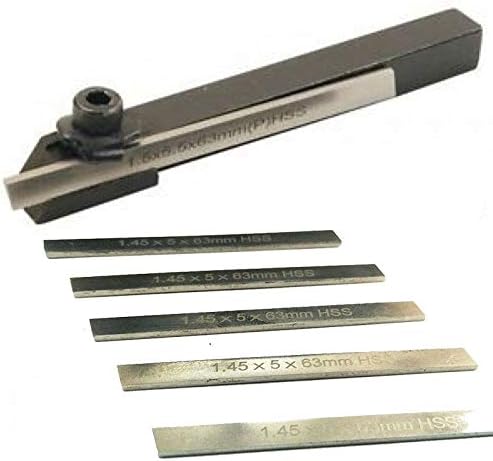
Due it small size I had to buy a mini parting blade and this is what it looks like below
Parting tool as supplied
The bit that’s supposed to hold the blade and keep it from moving is this bit, which is for all the world like a bent washer.
Flimsy Clamping fixture
After parting a few items off I noted that on some of them the back of the part was actually convex because the cutting force had bent the “washer” and allowed the parting tool to move to one side as it was cutting. Having bought my long length of steel from Wickes I decided that I would look at making something a little sturdier.
This is what I came up with.
Shop made clamping fixture
The slot is wider than the blade (1.45mm) because my smallest milling cutter at present is 3mm but I do have some brass bar that will fit in the remaining slot should I need to take out any slack.
Here it is fitted.
Shop made parting tool clamping fixture
There is a small shim in between the fixture and the tool holder which helps apply an even pressure. The fixture is thick enough not to bend under pressure and long enough to hold the blade inline with the tool holder without being able to twist while cutting.
Next I plan to make a locking handle for my tail stock. It currently locks via a cap head M6 screw which isn’t always very convenient.
I went through the process again this time drilling the offset at 2mm which proved to be perfect for this particular application.
I had been using a very thin cutting tool which someone had ground (not very well it turned out) which came in the box of bits with the lathe. After cutting the first one I thought that I would examine the tool to see if I could improve it or at least rub it on a stone to restore the cutting edge. When I looked closely at the cutting part I noticed that the bottom of the tool was wider than the top and although there was some rake away from the cutting edge the fact that it was getting thicker couldn’t be helping to make an efficient cut. This is a sketch of what the tool looked like originally albeit the bottom of the wedge is somewhat exaggerated. [img]https://live.staticflickr.com/65535/51259964196_7d3dd5c448_z.jpg[/img]
I have watched a few Youtube videos on sharpening lathe tools recently so I had a go at grinding the tool to take off some of the thickness towards the bottom making the two sides parallel. This improved the cut and I successfully cut the groove for the first sheave. Then I parted it off but I was a little too close leaving a very thin edge. During the parting off, the parting tool moved slightly in its holder which pushed over the thin rim of the sheave slightly closing the top of the groove. In the end it was usable but I decided to cut another pair to be on the safe side. It was while parting off the first one that I noted that my parting tool was in fact just the right thickness for cutting the groove without having to move the carriage as well as the cross slide to get the desired cut. Having discovered this the next one progressed much faster and modifying the fixture that holds the parting tool so that it grips the parting tool more securely by squeezing it in the vice made the third one even faster still. The parting tool is one like this albeit mine only has one tool. You will note that it’s a pressed steel fitting that grips the part with the aid of a cap screw. Mine didn’t hold the cutting tool very closely to the holder but it does now. https://images-na.ssl-images-amazon.com/images/I/41Uv-fAJmjL._AC_.jpg
So here we have the finished sheaves.
DA Princess Homemade EccentricsDA Princess Homemade Eccentrics
This is how they will fit on the axle once I work out their alignment with the crossheads further down the line.
DA Princess Homemade Eccentrics test fitted to the axle.
It turns out that I wasn’t far out with my 16mm deep offset hole, I had a measure of the remaining stock while putting this post together, and there is just about enough material to cut a 4th sheave had I needed a full set for a conventional inside motion build.
In my varied kit collection I have a few items of NER rolling stock from Medley Models/NER Days and it recently came to my attention via a fellow modeller that among other things the buffer heads in some of the kits need a little attention. I had a vague recollection of Steve Hoyle mentioning something about his supplier having supplied them as they are and has subsequently passed away so no chance of doing anything about them. These are what came with some of the kits (appologies for the slightly out of focus photos). You will note the interesting collar that would prevent any kind of compression…
I bought a couple of B1 opens from Mossy and they have been sat on my desk with the buffers beckoning to me each time I sat at my laptop. So this afternoon I decided to turn the collar off. In the end I did about 30 and it was quite a good exercise in repeatability on the lathe using the graduations on the lead screw handwheels although the minor variations in sizes proved that they weren’t done with a CNC machine. I also took the opportunity to file off any centre pips and rub over the heads with emery while I had them in the chuck.
Further to my last post, when the brass bearings arrived I knocked one up into a lubricator to see how I would do it.
It was a bit interesting drilling out the bearing but following advice given I got a short length of tube the same diameter as my bearing and made a slit in it to make a split collet. This I gripped in one of the collets on the lathe and then I centre drilled it. Followed by drilling right through. They are slippery little blighters and one flew off into space as I was attempting to load into the lathe collet. Surprisingly I found it a couple of hours later.
I was fortunate to have some 1mm square bar in stock so I drilled right through one way and then half way on one side. When I fitted the rod through the bearing and into the square section I filed half of it away for the last millimetre which gave me a bit more room to solder the piece in that goes into the boiler.
Globe lubricator from a brass bearing
With the obligatory scaling piece.
Globe lubricator from a brass bearing
As with all such things in modelling making one is sometimes the easy part making another or several is more difficult. So it proved with the second one
I ruined one bearing when I hadn’t quite tightened the collet enough and the bearing wasn’t centred, then I didn’t get enough solder on the cross pipe so that came adrift as I cut it short and I ended up having to re-drill it in the pillar drill before I could solder it back in.
But get a pair I did. My collection of bits for the D2 is slowly coming together.
A fellow Gauge O Guild member asked if I would tell him how I made the form tool for the whistles. Because I am a bit impatient* I was planning to make another one to turn Globe lubricators (if I could).
So, I made another form tool and took photos as I went along.
Using
a second cut file I filed away approximately half the thickness of the bar (in
the event it was nearer to 35/40% than half).
Then
I used a centre drill to drill a 1.5mm starter hold which I opened out to
2mm. I think my 2mm drill bit must need sharpening because I struggled to get
it to go through the last bit.
I
had drilled quite close to the end so I put the rod drilled end upwards in my
vice and tilted it forward to file away until I had just over half the hole
exposed.
Then
I transferred it to the lathe. I put my cone shaped grind stone in the
collet chuck and ground the inside of the hole to put my rake on it. The
black pen mark on the stone was at the 2mm diameter mark so I didn’t
inadvertently make the hole bigger.
Grinding the inside of the concave sectionGrinding the inside of the concave sectionGrinding the inside of the concave section
Next,
I used the diamond cutting disk to grind back the outer edges to refine what I
had filed and get it nearer to final size. But before removing the tool from
the cross slide I marked with a pencil the angle which I had ground at to make
replacing the tool at the right angle easier should it need regrinding.
Globe Lubricator form toolGlobe Lubricator form toolGrinding the inside of the concave section
Then
I hardened and tempered the cutting end. I did this by heating the end using my
Microflame to a red heat then I quenched it in a jar of water. I repeated the
process but only heating until it changed to a blue colour before quenching
again in water.
I
tried cutting a globe but I made a couple of mistakes:
The
material I was trying it on was too thin (2.5mm diameter) and I had predrilled
the centre thinking that I was going to thread a rod through it.
The
‘globe’ broke off long before it remotely resembled a globe and I realised that
even with thicker material I needed to grind more off the tool to make the
forming half circle shallower. At this point I used thicker material but still
predrilled it.
Another
try; another failure and another regrind.
The
last go was cut from 4mm bar and no predrilling and I also took some of the
edge of the ‘globe section with a diamond file prior to applying the form
tool.
Globe LubricatorGlobe LubricatorGlobe Lubricator
Having
done all this I now think that I may get away with thinner rod now that I have
refined the form tool and my technique.
Of course, the law of sod dictated that not 15 minutes after finishing the successful lubricator the postie came with some brass bearings that I had ordered from China and wasn’t expecting for another three weeks or so.* I an Middleditch in his original advice had suggested buying brass ball bearings and drilling them to make the globes from
The
subject of those will make another posting at some point.
While re-watching David LO Smith’s workshop video that he did for last years virtual show I was reminded that quite often the job itself doesn’t present the biggest problem for machine tools it’s holding the item securely in the right orientation that proves most challenging. Needing to drill out some cast brass brake hangers and shoes I was struggling on how to hold them because the castings were ever so slightly miscast meaning that each part had to be slightly tilted to get the hole to go through cleanly without coming out of the side of the casting. I thought I would share with you the method that I came up with.
I gripped the pliers in the small machine vice and bought the drill bit down in front of the part to check alignment, adjusting until the hole would pass through the casting correctly before aligning the drill bit over the point to be drilled. I have had these pliers for years and I removed the spring for a job and never put it back this means that the jaws stay where you put them so ideal for using both hands to do the set up. They have quite straight but quite narrow jaws (3mm for most of their length tapering to 2.6mm at the ends) and I wish I could buy another pair as using them for soldering many times has started to corrode the ends of the jaws. Then to start drilling grip the handles of the pliers to keep the part in place and operate the drill with the other hand. I had to keep minutely adjusting the angle as I drilled each end of each casting but all six were drilled both ends without mishap.
As promised on my J6 Build thread after bending the curves in the tender flares I took a series of photos using a piece of scrap to demonstrate how easy it is using a variation of a method described to me by someone on RMweb years ago.
He used the thick rubber heel design for replacing worn ones on shoes I use one of the rubber safe jaws of my Proxxon Vice.
First of all I just use the one soft jaw. You will note that the soft jaw has a thick triangular section that fits in the V groove of the hard vice jaw.
Bending Tender Flares
Opposite that to form the longitudinal curve I use one of the lengths of rod that came with my Metalsmith drilling table.
Bending Tender Flares
Next I fit the strip to have the flare bent in it into the vice between the soft jaw and the rod using the opposite V groove to hold the rod in position and ensure that the bend is going into the thickest part of the rubber soft jaw.
Bending Tender Flares
Once you are happy with the position tighten the jaws to create the bend
In this photo you can just see where it’s pushing against the thicker bit of rubber in the V groove
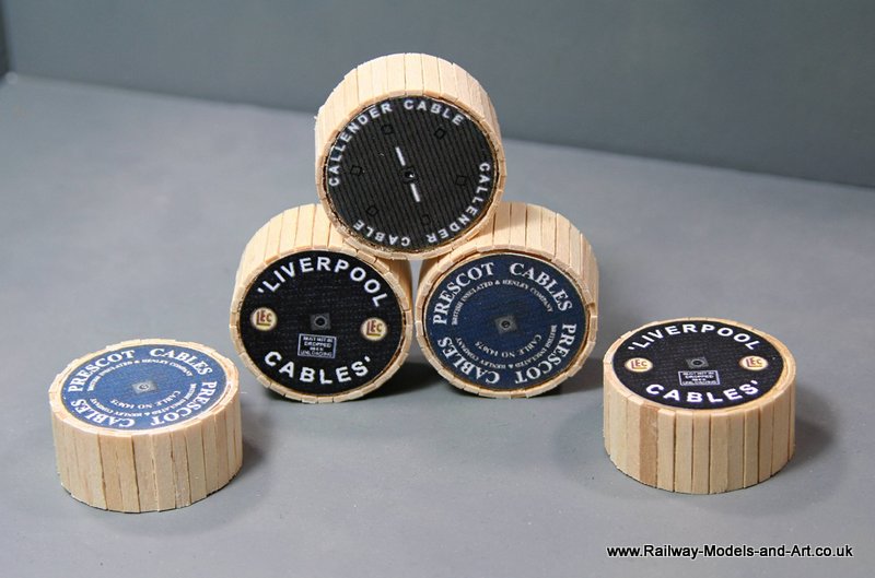
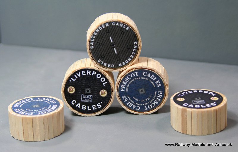
In a previous post on wagon loads(Here), I made some cable drums from wooden pieces created by drilling out lightening/cable runs on my layout boards and matchsticks.
Last weekend I came across a few more of the wooden circles and decided to see if I could improve upon them now that I have the NW Shortline Chopper to cut some coffee stirrers instead of the match sticks. An hour later I had 5 cable drums.
A quick resize, a visit to the printer and then some careful cutting out and I had some labels for them.
A couple of years or so ago I talk to Phil at Intentio about some occupied arches for my diorama board. At the time what Phil needed to charge to produce them was more than I could justify for a diorama for taking photos. So I left it at that and I pretty much forgot about it.
Whilst mooching around Telford we happened upon the LCUT Creative stand who had plain infilled arches and a couple of options of occupied versions all for just under £8.00 each. Having asked for measurements and worked out that three arches would create a backdrop for the diorama for just under £25 I decided that I could better justify the outlay.
Now it has to be said that they are made from a very thin fibreboard and can’t in any way be compared to what Phil produces but they will serve the purpose.
I had to use some of the offcuts as packing pieces to allow them to sit back against a piece of plywood that I cut to support them – this is because they come supplied with an internal sections which represents the inside of the parapet but I chose not to use is because I plan to use the spare pieces for something else.
Chris came up with the idea of printing of some old workshop scenes from the internet and sticking them behind the glazing on the windows and this is what it looks like before it get’s any paint on it.
One of the things that I have tried to do is to make as much use out of each drawing as I can. The NBR and the NER (I haven’t looked too closely at the other constituents of the LNER too closely yet). really help with this because of the many variations on a theme.
Using the example of the 8 ton Jubilee vans that I have just done I managed to use the artwork twice with minor amendments to make the matchboard version. looking a little further in vol 3 of Tatlow brought me to a 3rd and 4th variation this time in the guise of yeast vans same sized bodies, with both beaded and matchboard variations the only difference being is the added complication of louvres.
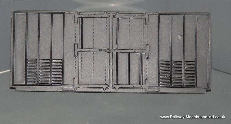
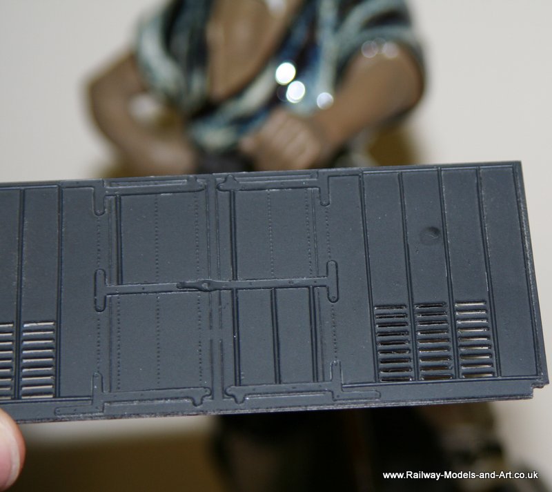
Since doing the louvres for the NER CCT I have studied and discarded a few methods of making louvres using combinations of styrene strip cut at angles etc. The flush sides of the louvres on the NBR vans gave me the opportunity to try another method which has far exceeded my expectations even if it is a bit time consuming to do.
This is where I have got to with the first van – or rather side of a van. Each side/end is made up of 3 layers and on the two inner layers I have moved the position of the louvre cut outs up by one pixel (I also marked each layer so that I knew which order to assemble them). To cut the slots I used an Exacto type chisel blade which was just marginally too wide for the length of the slot so I rubbed it on a diamond stone to reduce it a little.
To cut out the narrow end I used a suggestion from Graham (Beare) which was at the time for something else but applicable in this instance too. That suggestion was to use a piece of piano wire (0.8mm in this case) and file a chisel blade on one end I then gripped this in a pin vice and away I went – admittedly the patience only let me cut the slots in the 3 layers for one side at one session.
NBR Yeast Van
Please excuse the odd second photo I took it this way to illustrate that when viewed from a low angle you can see through the louvres but from the more normal side on view you can – JLRT…….
It still needs some beading finishing off and the other side and the ends need their louvres cutting out
Following on from a posting about wagon loads from household waste, albeit much belatedly, a gent on the guild suggested that the siphon valve wouldn’t really work as a load due to the size of the screw thread. That made sense and at the time I thought that it would make a load that could be sheeted if only I could make a suitable tarpaulin.
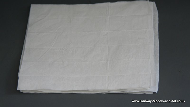
Fast forward to Ian G posting a link to an article on making realistic tarps (http://www.militarymodelling.com/news/article/making-realistic-tarps/3310) and I thought that I might have the answer. Sadly several attempts were made none of which were good enough to me. The first using Kleenex tissues just disintegrated and using the process on thin cloth worked but it wasn’t flexible enough. As a last resort I put a few lens cleaning tissues on one side after they were used to dry out and hey presto they worked.
This is what they look like after being ironed and treated – not much different in looks to be honest but they feel slightly thicker and have a texture. More importantly they can be handled/folded/stretched without mishap.
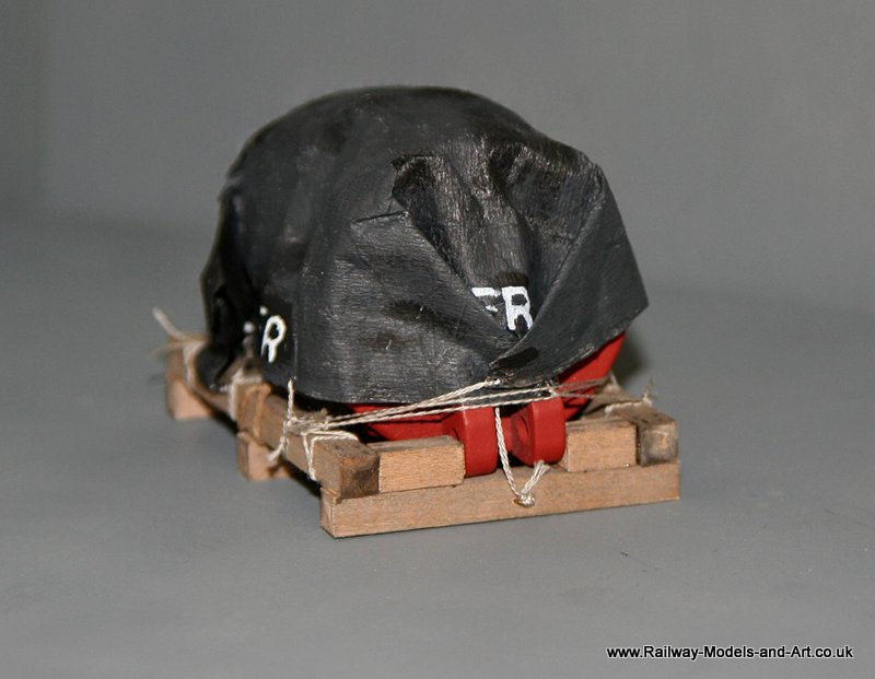
Next I cut some styrene discs using a leather punch and stuck them to a sheet to make eyelets. When they had dried I drilled holes through them and then brush painted both sides of the sheet black (the original plan was to spray them but I ran out of time last week). Next out came a cheap stencil and the letters LNER were painted on along each edge and some cotton cords tied through each eyelet.
LNER Tarp
In between this while things were drying, etc. I made up a timber cradle for the load.
7mm ScaleWagon load from Household waste;
Lastly I tied it all on – I had to add a couple of staples made from 0.45mm wire to the cradle ends to allow the sheet to be fastened.
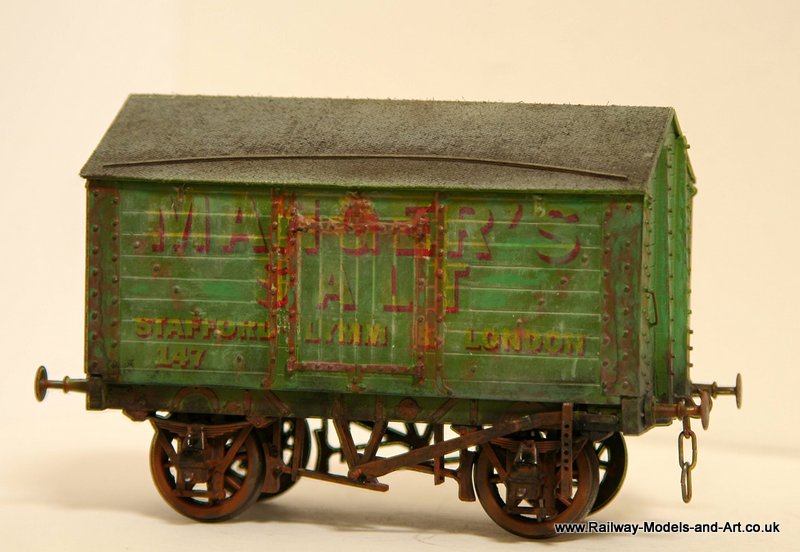
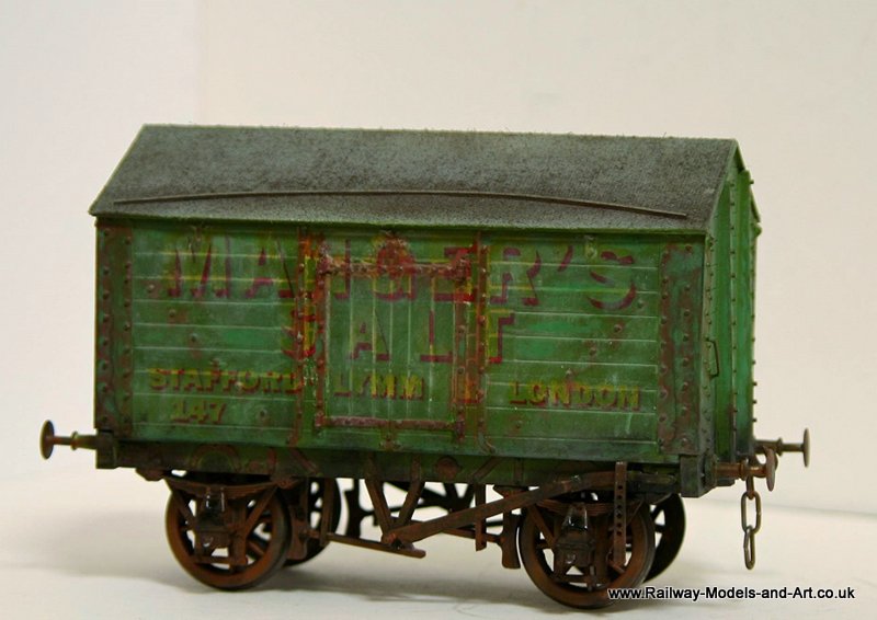
Over the last few weekends in odd moments in between gardening I have put together and painted another Slaters Salt van.
In contrast to the one I built earlier which was depicted as faded and worn I wanted this one to be in a recently out shopped version of the livery so I started by giving the wagon a good coat of paint (as opposed to the deliberately patch finish on the first one).
Slaters 7mm Scale Salt Van
Next I pondered on how to get over the fact that the transfers which are homemade and printed on clear decal paper have a tendency for the colour to wash out of the yellow when applied over a green base coat.
While it worked brilliantly for the faded livery it doesn’t for a newly painted livery so I thought that I would have a go at over painting the yellow bit of the lettering by hand.
I used Vallejo Sunshine yellow but found that it took a few coats to get it to cover on the slippery surface of the transfers. In all it took six sessions over two weekends to do both sides it’s far from perfect but I am happy with the results and I will use the technique again.
Last night I had a mess about with image stacking – I am quite pleased with the results so far. Each final image is made up from 5 original images combined into one.
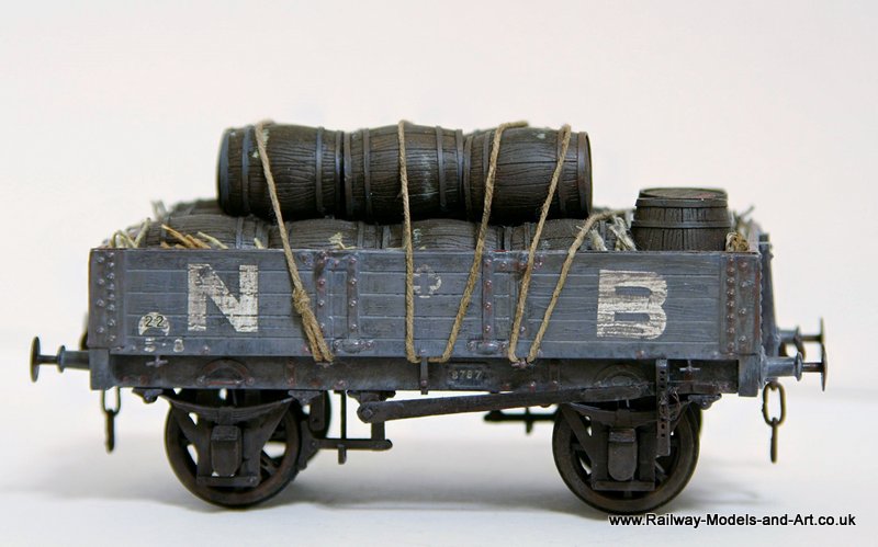
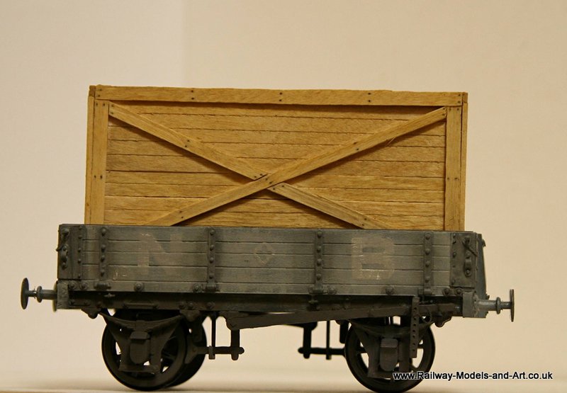
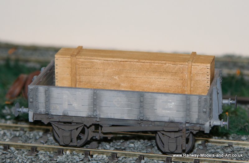
I have been tinkering around painting some of the wagon loads that I have made from coffee stirrers and thought that I would share them posed in my latest wagon.
Scratch Built NBR 4 Plank Dropside wagon with assorted scratch built timber loads
Scratch Built NBR 4 Plank Dropside wagon with assorted scratch built timber loads
Scratch Built NBR 4 Plank Dropside wagon with assorted scratch built timber loads
Scratch Built NBR 4 Plank Dropside wagon with assorted scratch built timber loads










![[img]https://live.staticflickr.com/65535/51259964196_7d3dd5c448_z.jpg[/img]](file:///C:/Data/Build%20Commisions/DA%20Princess%20-%206206%20Princess%20Marie%20Louise/%5bimg%5dhttps:/live.staticflickr.com/65535/51259964196_7d3dd5c448_z.jpg%5b/img%5d)