The wind dropped enough for a couple of short bursts of painting outside. This enabled me to get the chassis primed and then top coated. I also did all the other little bits that I missed when doing the body and tender, fall plate, doors etc.
Brakes and other bits got a coat of paint too.Gladiator J6 Loco Chassis Painted
Before risking gumming up the motion I asked Warren Haywood and Tony Geary how they painted inside motion. Tony hand paints his and Warren sprays it. Warren did suggest that since the brief for this is weathered black rather than red to metal black it. Thinking this a good idea I had a go. I gave the chassis a liberal dose of acetone to hopefully remove all the oil then a liberal dose of Birchwood Casey Brass black. It kind of worked, the motion itself looked fine but the insides of the frames and motion plates etc. were quite patchy.
In the end I bit the bullet and lightly sprayed it with black etch primer. Thankfully it all still moves as it should but I did mask it before putting the final coat of the rest of the frames.
Contrary to my last post I decided to see if I could make the motor mount removable. It proved not too difficult to add a screw and retaining nut to the adjacent frame spacer.
Motor Mount Screwed in and wiring harness stuck to it.Motor Mount Screwed in.
The motor mount also made a convenient place to mount a piece of Vero board which means that I can now remove both the motor and mount together without having to unsolder any wires which I count as an unexpected win.
The hole in the tender plate which supports the bottom end of the pivot pin was much bigger than the screw itself (8BA) and after fiddling around for about 10 minutes trying to get the screw to engage in the nut I decided to turn a small bush to centre it.
The hole was too big for the screwCustom turned drawbar bush.Drawbar held in by custom bush which helps locate the screw in the hole.
I am getting dangerously near to painting the chassis.
Not too much done on the J6 this week but it’s almost there now.
I had a bit of a fright when I fitted the motor and I couldn’t get the body on but thankfully I had just put it in the wrong way round.
What it did need is a motor mount/steady to stop it moving backwards and forwards inside the body. I cut a small piece of nickel sheet as a slding fit between the frames and then cut out the mounting hole. I worked out where I needed to fold it and then decided to give the bending shear on the MiniFormit a try. I am pleased o say it bend it perfectly. Not being used to using it, to make bends. I didn’t follow the bend through to a right angle. instead I finished it off in my hold and fold.
Over on Western Thunder there was some discussion on the merits or not of Slaters Plunger pickups from a gent who had used them for the first time I mentioned that I was about to wire up the tender for the J6 with Slaters Plunger pickups and I offered to take photos as I went along. I thought they may be of use to someone else who may be contemplating using them but hasn’t seen them before
First I guesstimated the lengths of wire needed to reach from the plunger to the connections on a piece of Vero Board. These I soldered to the tags provided with the plungers
Wires soldered to tagsMini Plug and Vero board
Connection between the tender and loco is to be by a mini plug sold for PC’s and bought via eBay some time ago.
One thing that makes life a little easier when dealing with the 12BA nuts on Slaters Plungers is a pair of flat 12BA spanners available from Eileen’s Emporium
12BA Flat spanners for tighening the nuts on the plungersWires in place ready for soldering to vero board
Here it is all wires connected to the plungers and ready to solder to the Vero Board
J6 Wired Chassis
Finally all wired up. – The observant amongst you will note that the size of the Vero board has changed in the last photo. I made a right pigs ear of soldering the first piece managing to bridge the gaps between the strips with solder so I did it again. Thankfully I hadn’t got all the wires on before I cocked it up.
I got to fitting the rest of the 3D printed brake shoes to the J6 brake hangers today and then refitted them onto the pull rods. I don’t think I have shown the loco sat on the body since it’s pretty much complete. Just a few final bits like wiring it up and testing it before painting the chassis and weathering the whole thing
I wasn’t really happy with how far away from the wheels the brake shoes needed to be to ensure that they didn’t short. I rew up some brake shoes in Fusion and a friend kindly printed them off for me.
Today I had the chance to test fit one of them. After checking that I hadn’t messed up and that the etched hanger would go between the flanges. I bit the bullet, unsoldered the etched overlay and cut of the brake shoe from the hanger.
The next question was how to attach the printed brake shoes to the hangers. I hoped to have the shoes free to move and after considering and discounting various options which involved superglue I settled on a dressmakers pin and short length of microbore tube soldered to the pin and then filed down.
Gladiator J6 3D printed brake shoesGladiator J6 3D printed brake shoes
A couple of weekends ago I was demonstrating Loco building at the Stainmore Railway Model Railway show. I took along the chassis for the J6 and had it running on the rolling road all weekend. Besides giving the motion a really good bed in it attracted a lot of attention.
So much so that I plan to make up another chassis with inside motion for my demo stand.
On the back of a great weekend out I decided to see if I could crack the construction elements of the J6 last week. The remaining jobs were.
Fit glazing Add Milliput to the back of the balance weights to make them solid rather than just an etched front. Fit the sand pipes Fit the remaining linkages between the brake pull rods and the brake cylinders Fit some Frame extensions under the boiler between the front pairs of wheels to hide the rear of the wheels – following Tony Geary’s lead.
Gladiator J6 Balance Weights
Balance weights, I added a coat of primer to bled it all in before final paint and weathering.
Brake cylinder cranks
The first bit of the brake linkages
Gladiator J6 Sandpipes and false frame tops
Front sandpipes and Frame extensions. Before fully soldering them in I tested the frame extensions at one side by tacking them in and the seemed perfect. But the chassis mustn’t have sat down properly because I noted while testing for clearance on the rear sandpipes that they need trimming down a bit.
Gladiator J6 Rear Sand Pipes fitted
Rear sandpipes. I had to fit the tops of them very close to the frames to avoid the injector pipework but I got there after two or three adjustments.
Gladiator J6 Rear Sandpipes and brakes linkagesGladiator J6 Rear Sandpipes and brakes linkages
Last but not least a couple of shot of the remaining brake linkages. Although soldered at the rear the ends of the rods are a loose fit in the turnbuckles so allowing removal of the brakes.
A bit of a milestone was reached in the Pulham household last night. I have been tinkering for a number of days with the inside motion, getting it all to fit in the frames. I had to mill the inner side of each crosshead to clear the eccentric straps etc. so they are now handed and I also had to enlarge the centre section of the motion bracket to allow the assembled eccentric rods, expansion links etc to pass through it. Then came the final job of determining the length of the connecting rods and cutting them to length.
Once they were cut and tried in place the length was right but they wouldn’t fully rotate because I hadn’t made the slots in the motion bracket deep enough. Much filing and testing ensued but I didn’t seem to be getting anywhere and then I realised that because of the constant assembly/disassembly for testing, I had the frames upside down. What I was viewing as the top was in fact the bottom so I had been adjusting the wrong side. More filing and test ensued and I got there in the end.
Having tested the pistons successfully with the valve parts resting outside the motion bracket I put it all together inside for a further test.
This week has seen more work on the J6 most of which isn’t really photogenic as it’s been to do with assembling and fitting the inside motion which isn’t quite there yet.
In order to assemble much of the motion I needed some pin so I decided to turn some taper pins from 0.9mm nickel rod.
Taper Pins
Having touched up the tool of a stone and got myself into a bit of a rhythm, I soon had a dozen or so ready. I only remembered to take a picture after I had fitted most of them…
Whilst pondering on aspects of the fitting of the motion, my thoughts turned to the remaining jobs to be done and one of those is sand pipes.
A quick check on Laurie Griffin and Ragstone site’s didn’t reveal much in the way of sand pipes so I decided to make my own.
I started by checking sizes on the GA and settled on some 0.8mm rod for the pipe itself. I had a length of microbore tube that fitted over it and used that to make the body of the fitting where the steam pipe attaches.
Gladiator J6 Scratch Built Sand pipes – Stage 1
I started by filing a notch in the pipe such that with a slight bend to the remainder I could feed the ‘pipe’ through the sort end giving me an angled branch.
Gladiator J6 Scratch Built Sand pipes – Stage Two
Next I filed an angled flat on the end of the tube to create the other branch of the fitting.
Gladiator J6 Scratch Built Sand pipes – Stage TwoGladiator J6 Scratch Built Sand pipes – Stage Two
Some home made nuts/unions and 0.45mm beading wire for the steam pipe, completes the job – x four of course
Still making slow but steady progress in between with the J6. The tender is now coaled and ready for weathering. I plan to weather the loco and tender at the same time so that I get them looking the ‘same’
Needing a bit of an escape from recent forum politics and not wanting to do anything that required too much in the way of thinking I made a start on ‘teaking’ the full brake.
Working from a photo I found on the web I darkened the ends and some upper panels on each side using Vallejo Burnt Umber applied by flat brush and then a few other panels were darkened using Vallejo Flat earth which is my go to colour for LNER coaching stock brown. This is lighter than the burnt umber but darker than the Just Like The Real Thing teak undercoat.
Then I made a start on adding the many layers of Ronseal Teak interior varnish that will eventually make up the coach finish.
The Start of the teaking process on the JLRT BGJLRT BG Start of the teaking process
Once all the varnish is applied and I am happy with the overall finish I will mask off and spray the roof.
While working on the brakes I made a small discovery which made things a bit awkward. When rebuilding the springs and dampers from the original Ragstone castings I had set the dampers much too low under the springs. That combined with them being slightly over size and a few of them not quite being round meant that when testing the wheels rubbed on them and the brake pull rods wouldn’t seat properly.
An easy fix I thought. I will turn up some slightly smaller dampers which will be round and it should be an easy job to pop the dampers off and reseat the replacements flush under the springs.
Oh no when I tried to get the dampers off I ended up pulling the whole thing apart
Gladiator J6 Original Ragstone Spring Dampers
Replacements duly turned I also decided to add the quite prominent nuts on the bottom
Gladiator J6 Replacement Spring DampersGladiator J6 Replacement Spring Dampers
I decided it would be easier to just assemble the dampers onto some new pins and then fit them to the springs and hangers
Gladiator J6 Replacement Spring DampersGladiator J6 Replacement Spring Dampers
Next comes what for me has been the trickiest bit of the build so far.
The bending and fitting of the two dropped curved ends of the footplate. These are full thickness etch and at0.45mm in Nickel they take a bit of bending.
First I fitted the valences using a piece of square bass bar and some surgical clamps to hold it in place and vertical to the footplate. Just a case of tack in several places along the length and then seem between them.
Next on to the dropped sections, I started with the rear section for no other reason than the front section needed the rivets pressing out and I had done enough of that for the day when I finished the footplate earlier in the day.
David Andrews Princess Valances fitted ready for the front section of footlate fittingDavid Andrews Princess Valances and foot plate rear
I marked up the start of the bend and another line which should have been the middle of the bend but fell somewhat short. In the event this wasn’t an issue as by some miracle I managed to bend it almost perfect first time. It just needed a gentle bash with a rubber mallet to get the last bit of the curve where it meets the footplate to the right shape.
David Andrews Princess Valances and foot plate rear
While I was on a roll, I added the drag beam too.
Then it was more rivets prior to fitting the front section
David Andrews Princess Foot plate Front Ready for Bending to shapeDavid Andrews Princess Foot plate Front Ready for Bending to shape
As I mentioned in the Princess Build Post in between punching out rivets which is a little tedious to say the least I have also done a bit more on the brakes for the J6
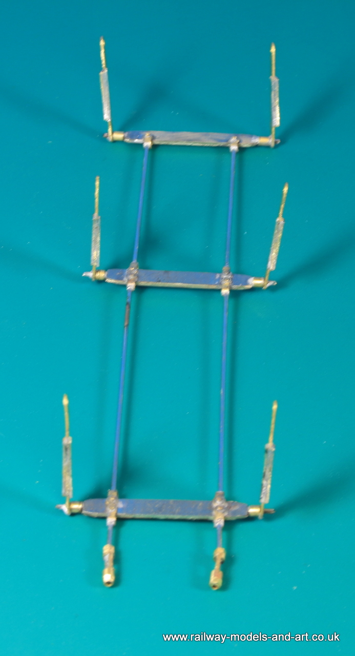
The brake hangars are single layer etches and being an older hand drawn kit the holes are a bit on the big side for lengths of wire. I also wanted to make the brakes removable so I turned up some hangar brackets cum spacers.
Gladiator J6 Brake spacers
These are soldered to the chassis and the brakes hang off them.
Gladiator J6 Brake spacers fitted
This meant temporarily re fitting the wheel, and spring hangars (so that the axles didn’t keep falling out.
Gladiator J6 Brake Assembly
Which allowed me to make up the brakes and have them removable. The GA drawing shows that there were turnbuckle type adjusters at the cab end so I knocked a couple up on the mill.
I also fitted the brake cylinders which requited yet another frame spacer to be milled out…. That seems to be a theme at the minute.
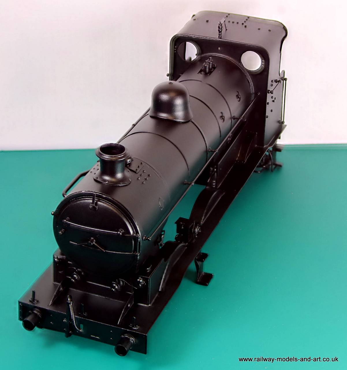
The sun shone again over Wensleydale this morning so I took the advantage to get the top coat of cellulose on the J6. This is without doubt the best results that I have ever had from rattle can paints. – ‘Clostermann’ cellulose Satin Black
Gladiator J6 Top coat onGladiator J6 Top coat onGladiator J6 Top coat of paint onGladiator J6 Top coat of paint onGladiator J6 Top coat of paint onGladiator J6 Top coat of paint onGladiator J6 Top coat of paint on
Then the world turned black. I had initially primed the tender body a couple of weeks ago when the sun last shone. I took the opportunity of sun here in the dales to get the body primed yesterday afternoon. I am greatly impressed with the finish of the Clostermans etch Primer. I have used it and the cellulose top coat before but only on loco chassis and you don’t really get the same effect. It’s also an absolute b***r to light properly for decent photos. These are my third attempt.
Gladiator J6 Loco Body PrimedGladiator J6 Loco Body PrimedGladiator J6 Loco Body PrimedGladiator J6 Tender Body PrimedGladiator J6 Tender Body PrimedGladiator J6 Tender Body PrimedGladiator J6 Tender Primed