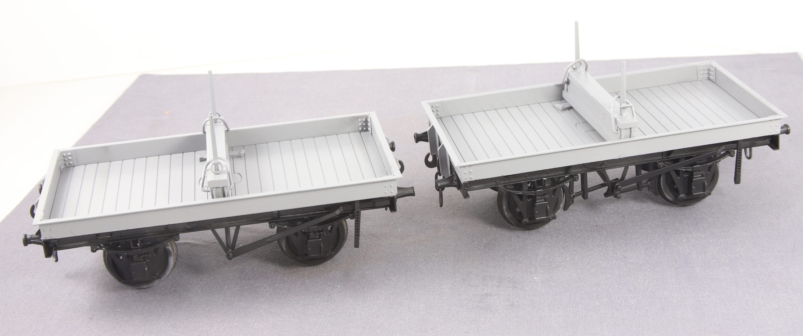
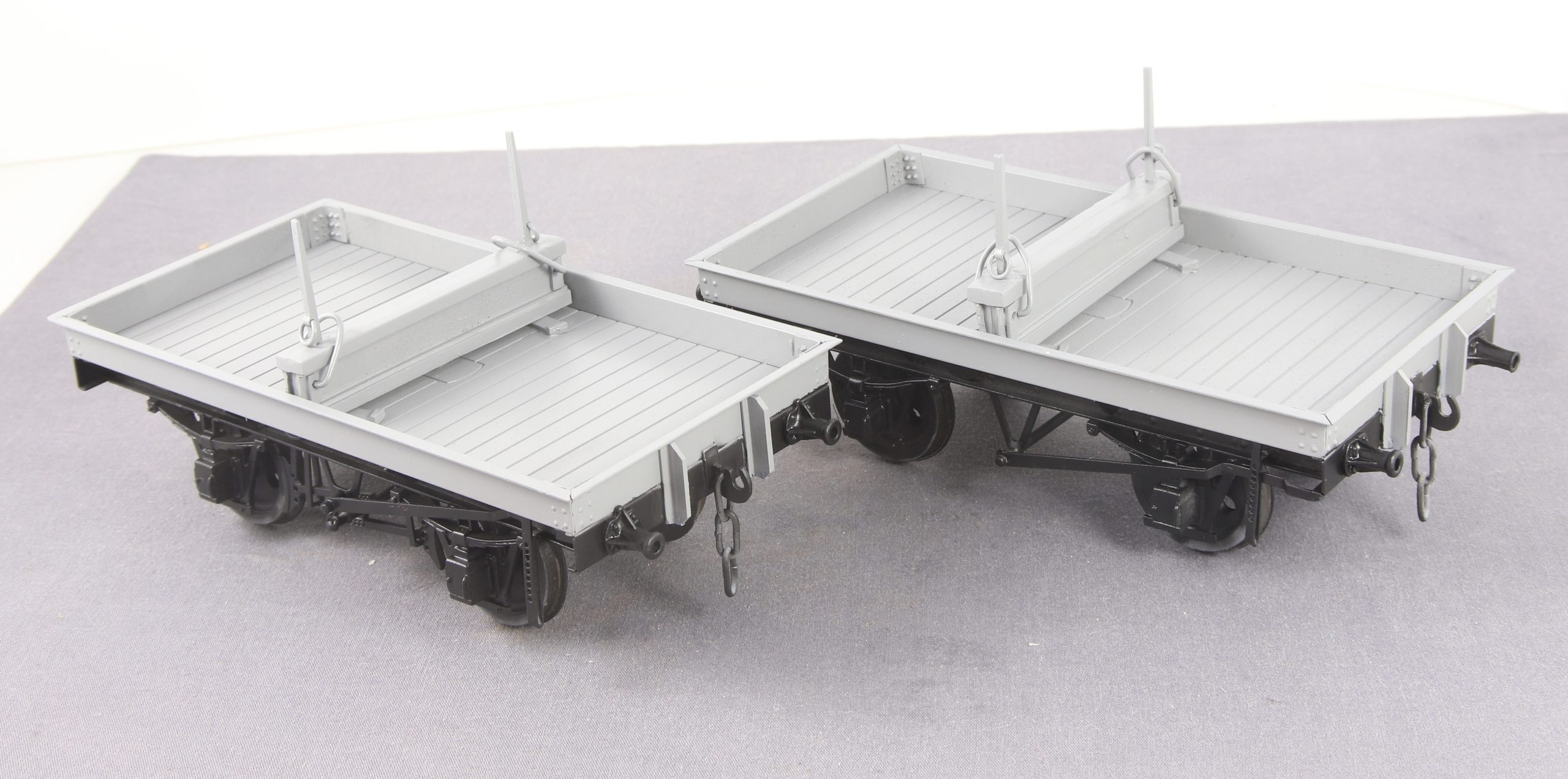
While I was in the mood I got stuck in and masked up the bolster wagons ready for spraying the underframes. I had already sprayed the top coat on the upper bodies on Friday but didn’t take any photos as they looked no different from when they were in primer.
With the solebars being black on these Steel bodied wagons, it made masking up so much easier that wooden bodied vehicles where the sole-bars are body colour and you have to work around brake levers and lever guards etc. when masking.
Speaking of which that’s the next job, as I am also on with painting some NER vehicles for a friend at the same time.
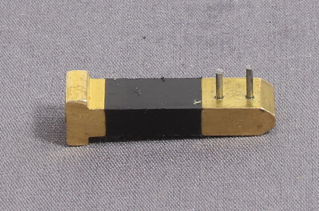
Needing to make a number of hooks for the shackles and the ends of tie down chains I decided to make another jig. Initially I made up a couple of hooks to gauge the length between the bends then I drilled a couple of holes in yet another plug pin and added some piano wire. i confess that I was very sceptical about how well the piano wire would hold up being quite thin at 0.8mm but in practice it’s been more than fine.
Hook Bending Jig
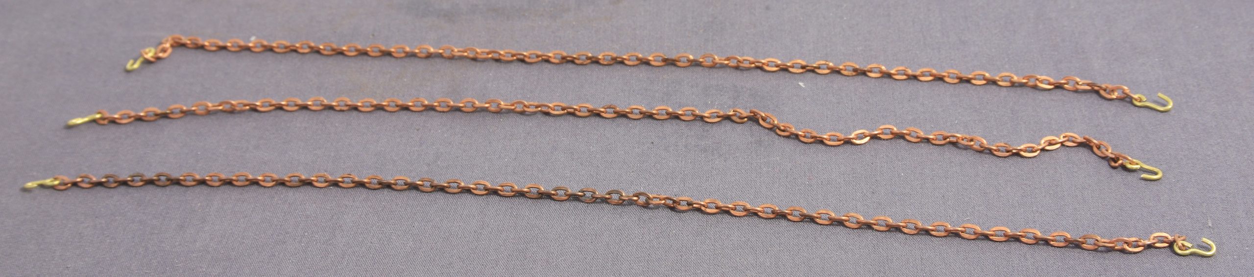
Once I had made a few I cut some lengths of copper coated chain that I had left over from a Connoisseur kit and fitted hooks to each end
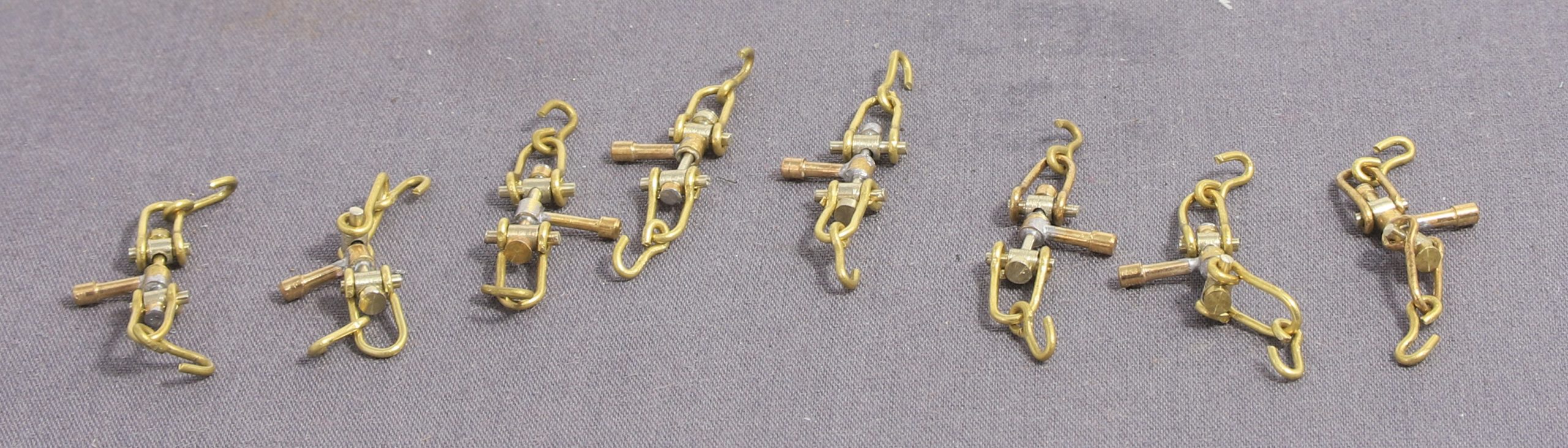
Finally I started adding a hook to each end of the shackles. like making up the D links it was another steady but quite therapeutic job.
Now that my Bolster wagons are nearing completion my thoughts turned to loading it and by good fortune my good lady had recently trimmed out apple trees. So I found a couple of stout branches amongst the offcuts which looked like they might make suitable timber loads.
The next thing was how to tie them down and I decided to have a go to see if I could make some screw shackles – think screw couplings without the hook for the vehicle body.
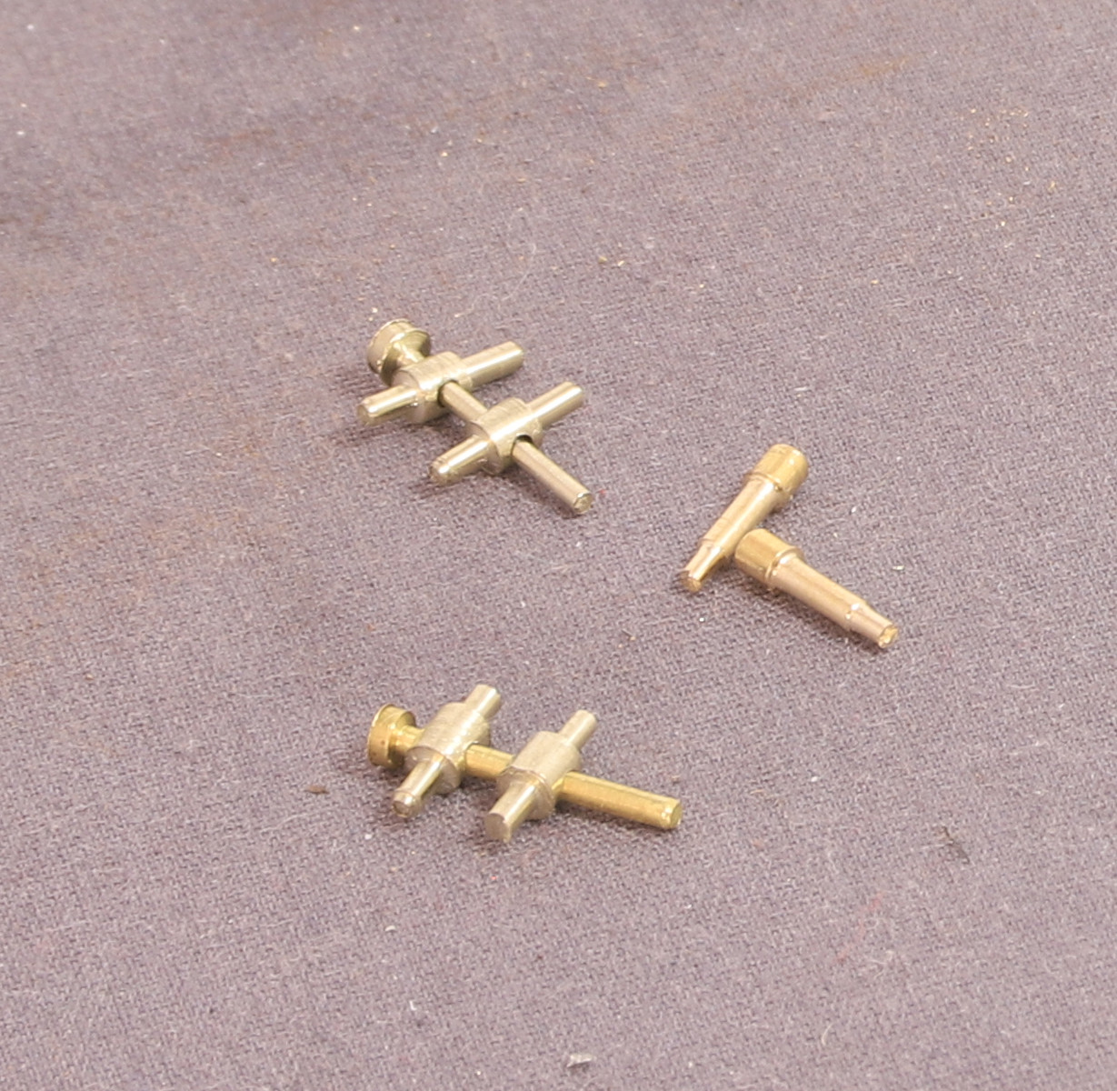
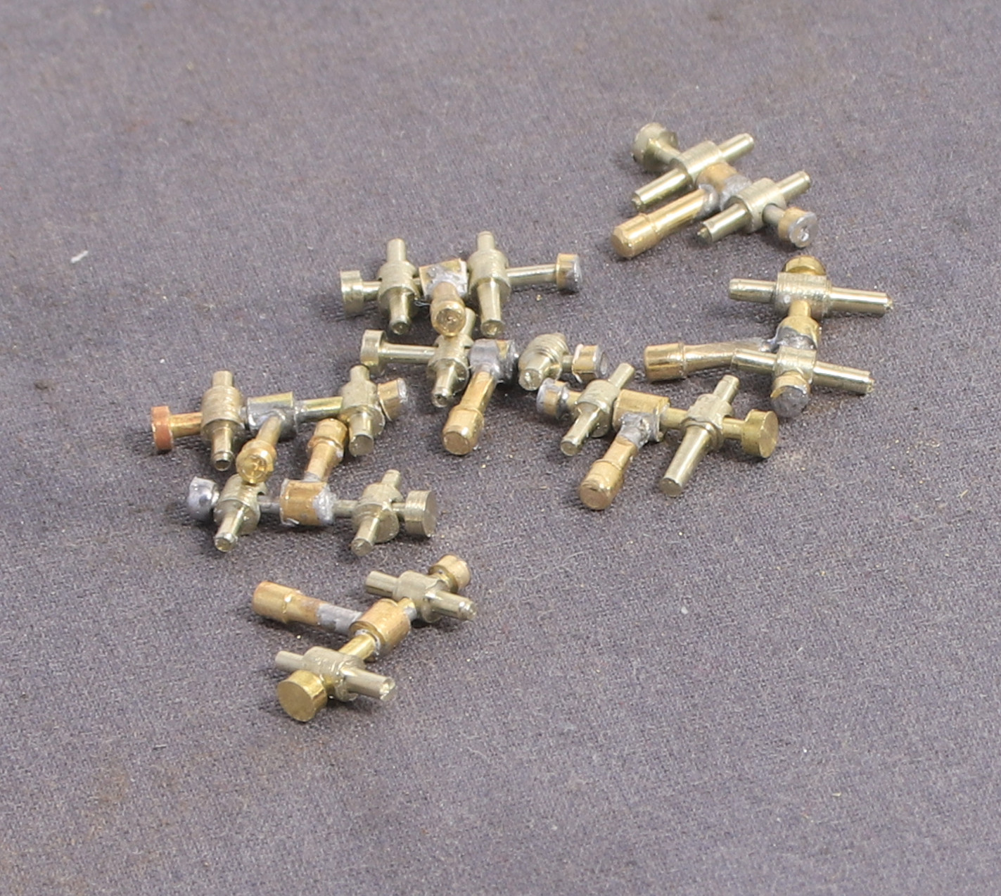
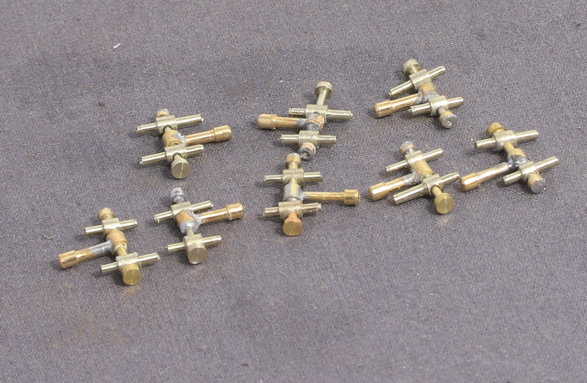
I started by making what I call the trunnions and centre pins lots of small turnings. Some of them were cross drilled using my Proxxon mini pillar drill. The major diameter of the rod is 2mm and to centre the drill on the part, I popped a 2mm drill bit in the chuck upside down and dropped that in between the vice jaws.
I made the bob weights from 1.6mm rod which was turned down to 1mm nominal for the shaft but in hindsight I should have made them a little bit thinner.
I drilled and them cross drilled more 2mm rod to make the bob weight collars but since making these I experimented with making the collar and centre pin as one piece and in future when I make more I shall do that as soldering the bob weight in, and then soldering it central on the shaft was a bit of a pain.
The final piece was a small washer to retain the other trunnion.
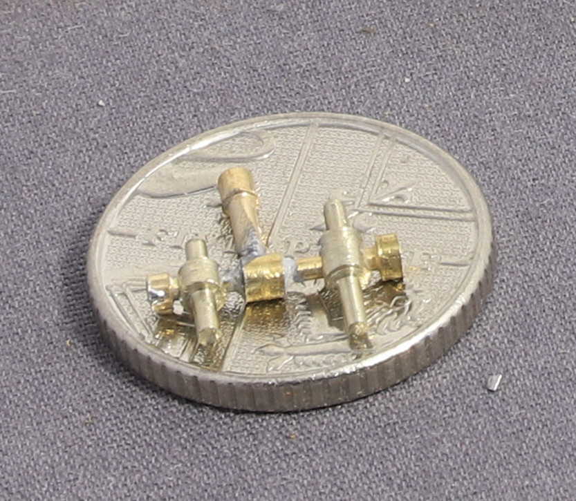
And with the obligatory 5p piece for scale. magnified so much the solder looks a bit messy but it’s barely visible at normal viewing distances.
Finally I had to make up the D shackles so I made a bending jog to ensure that they were all pretty much the same size.
D Shackle Bending Jig
The jig is made from another redundant plug pin with holes drilled in to determine the length between bends with short lengths of 0.8mm piano wire loctited in to create the pivot points. The observant amongst you will note that initially I drilled a third hole to insert a tail to start the initial bend but after doing the first one I realised that it was much more efficient to make the first bend with a fine pair of round nosed pliers then placed the formed eye on the jig to bend the other end.
D Shackle
I made four pairs in this session of making them. All that remain are hooks to attach to the chains.
This post is a bit in reverse order of what I’ve been up to in the last week with the latest first because it follows the previous post better.
The chance discovery of a part can of Halfords grey primer in the shed and yesterday’s cold, but dry and windless conditions, had me dig out my outdoor spray booth (aka a big cardboard box that sits on the dustbin) and prime the bolster wagons.
Now the replacement spring has all but disappeared into the background and I suspect if I don’t mention it casual observers will be none the wiser.
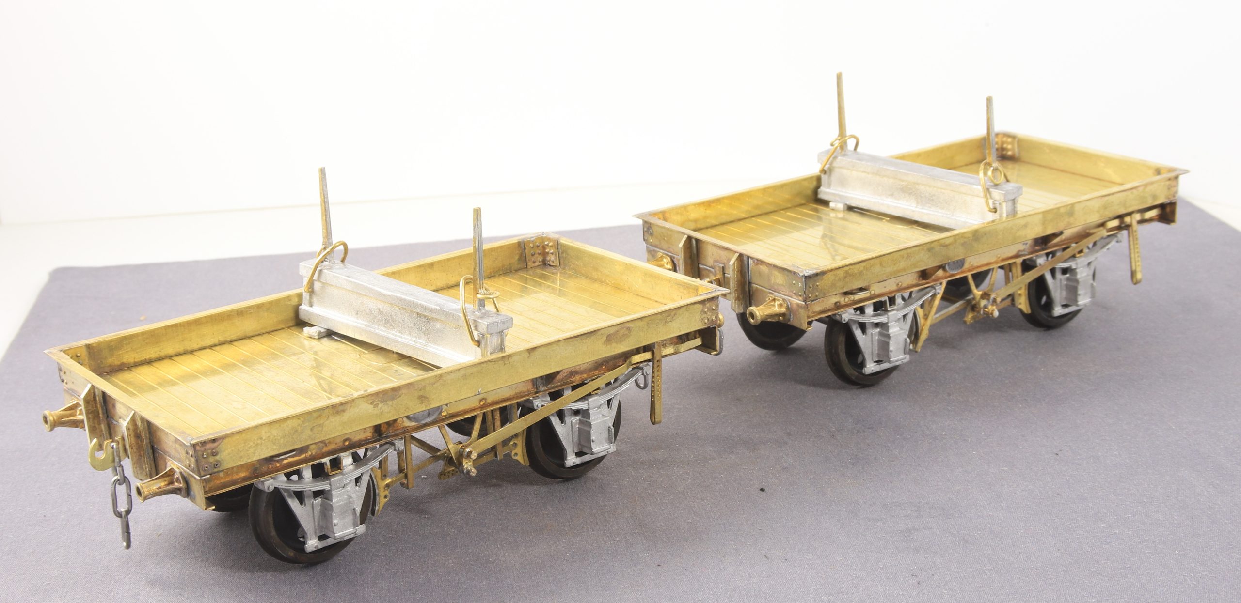
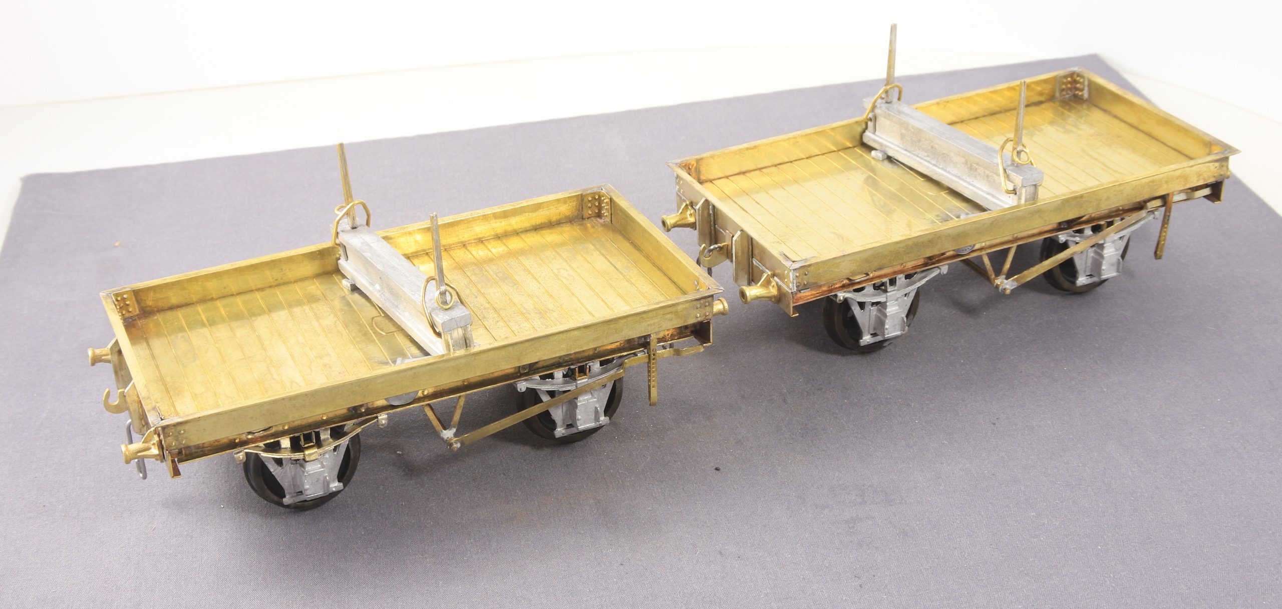
Inspired by a friends recent photos of his Connoisseur Bolster wagons I kicked myself up the backside and finished my pair of jim’s bolster wagons that I have been slowly making as a demo piece at shows last year.
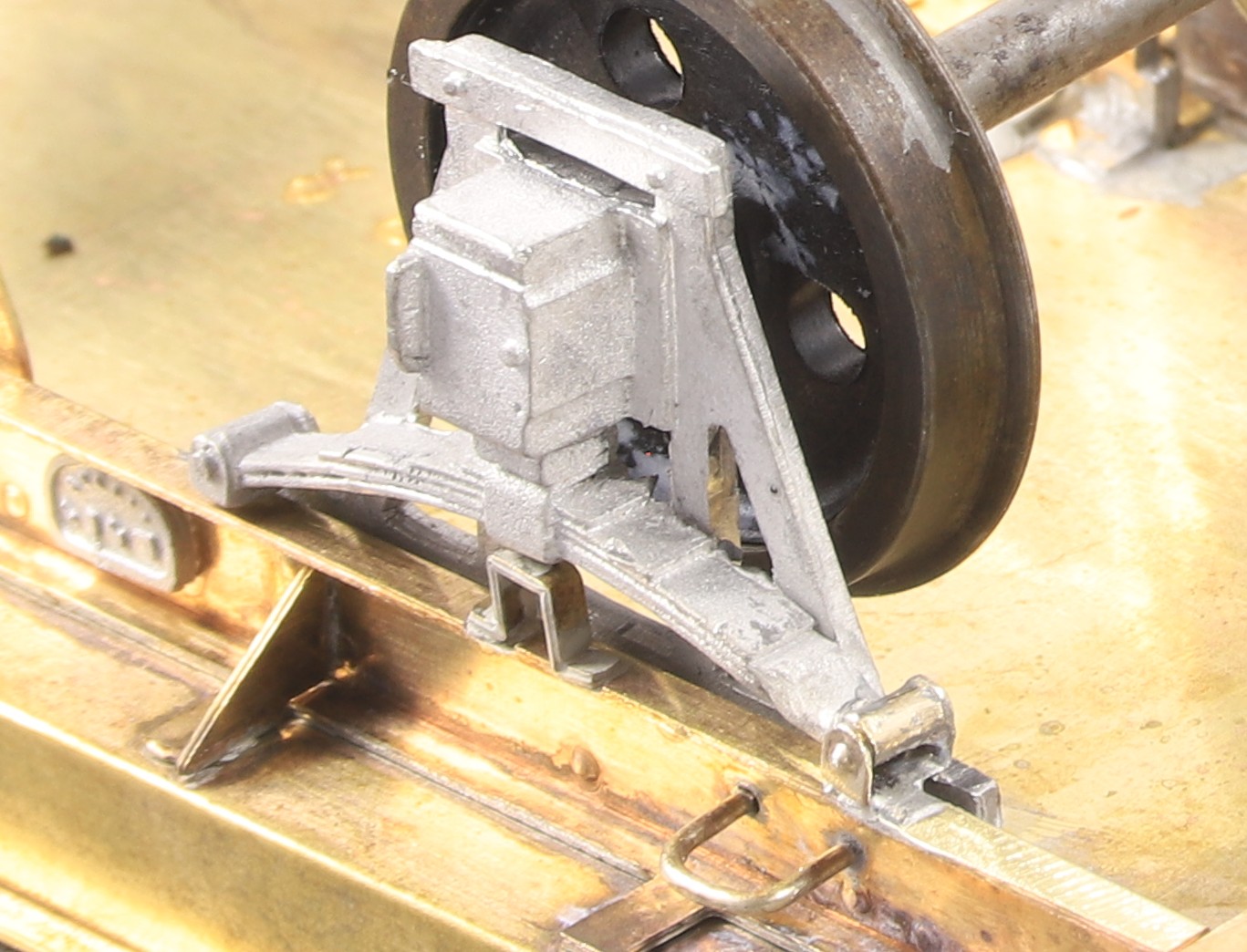
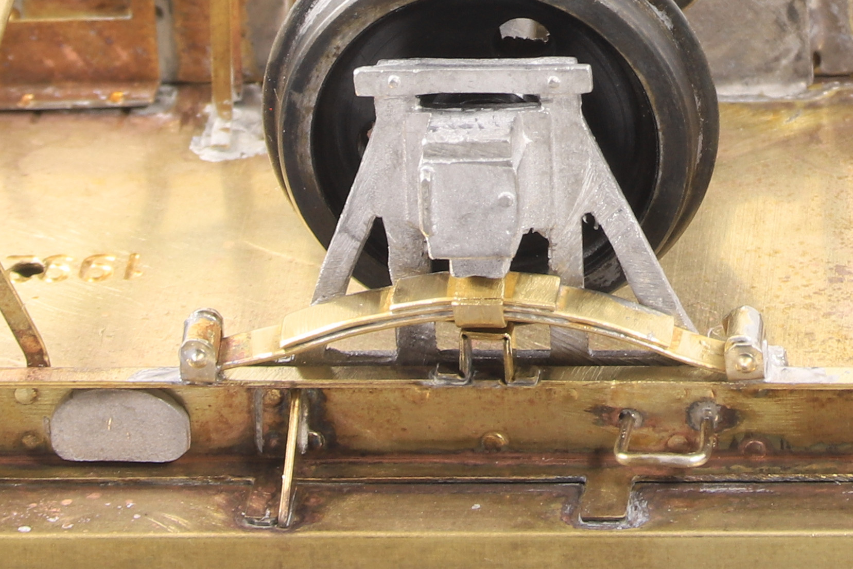
As these things go I took the pretty much completed wagons along to show a friend who has recently finished a lowfit and he noted that my axle guards splayed out slightly, which I confess I hadn’t noticed. But as I said to him, I would rather find these things during the construction phase than after painting so I set to and removed one axle guard from each axle choosing to use the unbraked side as being easier to get at. One of the bearings wasn’t seated properly so I deepened the hole. However they still looked splayed out. so I filed the pin points off both ends of the axle. This fixed the problem.
As ever this didn’t go quite as smoothly as I’d hoped as on two of the four axle guards castings that I removed, I did managed to damage them. The first was just one of the spring hangers broke off after I stuck a screw drive under it to prise as I heated up the body to soften the low melt. As luck would have it, when making some different anvils for my Leakey rivet press I had done some test rivet strips and one of those had just the right spacing to make some new hanger brackets from. A short stub of 1.6mm rod in between and we have this.
Sadly on the other one I wasn’t quite so lucky in that in a moment of inattention with the microflame I also melted the spring as well as the hanger. So I set to and made a pair of hangers and the spring to go in between.
On a side note I also fitted the D plates with the microflame. I tinned the backs with 100 degree solder and placed them on the solebar. Then I wafted the flame on it’s lowest setting along the bottom of the sole bar until I noted the D plate starting to settle then I took the heat away.
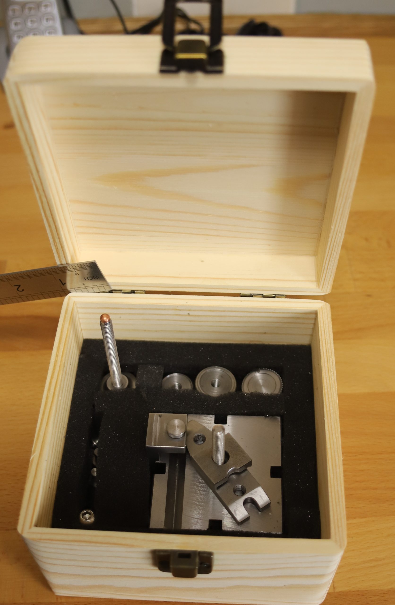
Needing something to store my newly constructed Finger plate in. I initially looked at wooden boxes sold by “The Works” (after a recommendation by a fellow Guild member). However when I looked at them, they may well be good for storing rolling stock in which is what the recommendation was for, but they are far too flimsy to store reasonably heavy tools in.
Chris took it upon herself to look for alternatives and found some on Amazon. Although they offered a 20% discount if you bought five, I opted to buy one at £6.99 to see what they were like.
The box arrived today and I have to say that I was impressed. They were £2 more than those at The Works which had actually been reduced from £6.99 to £5 but they are much more substantial. I cut some foam to create some packing around the finger plate. It’s a little too short in height to hold it with the jack screw fitted but that’s not the end of the world.
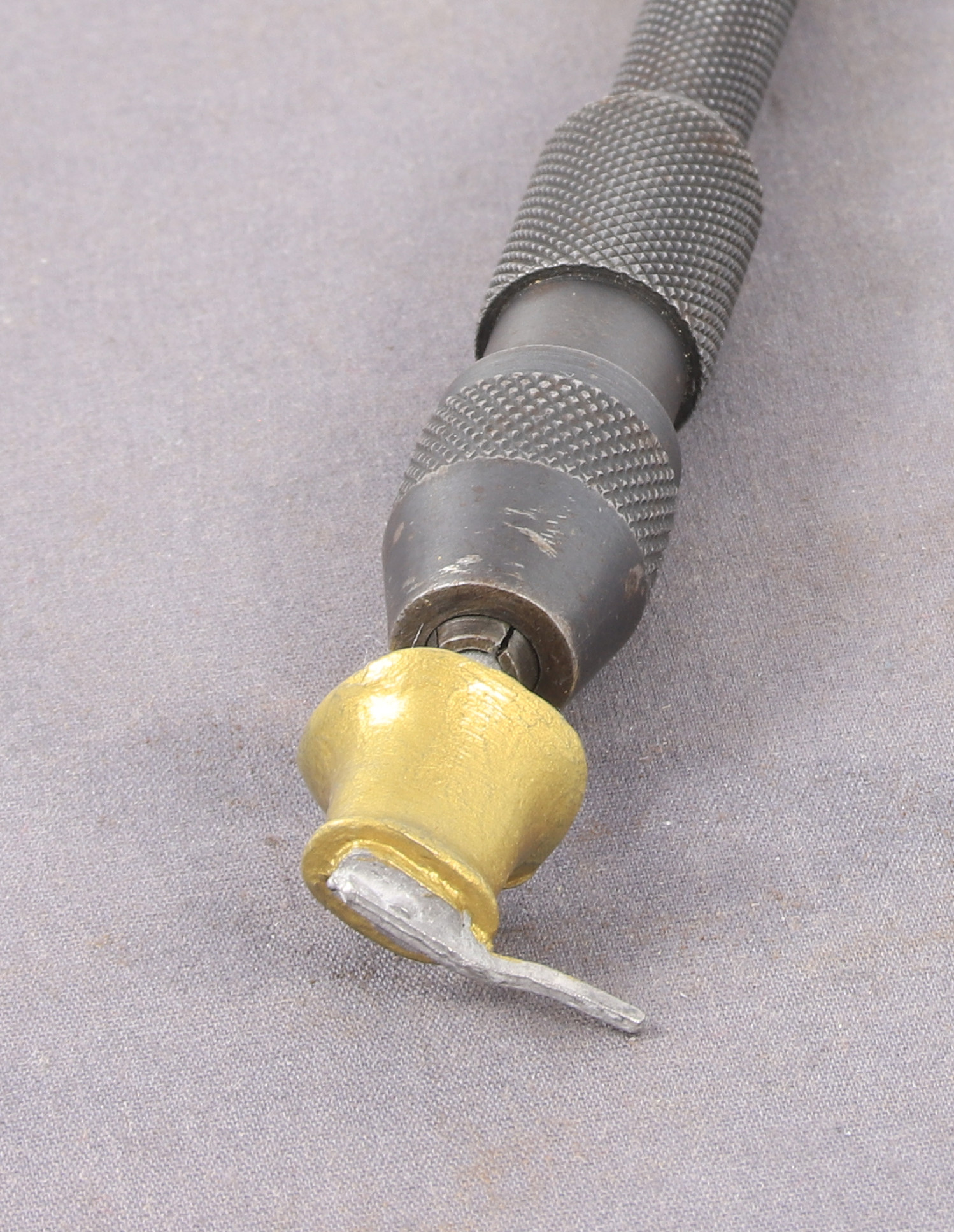
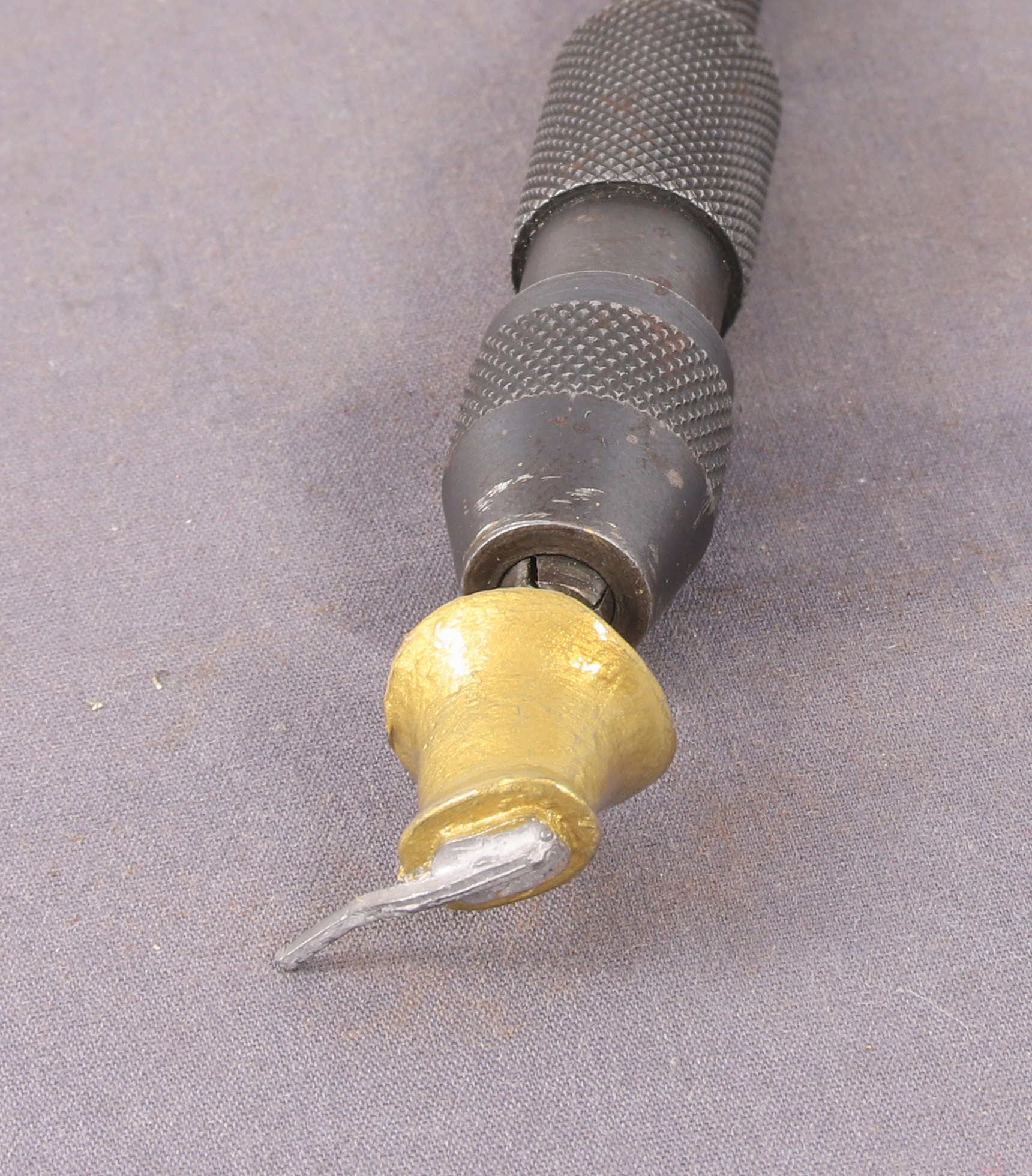
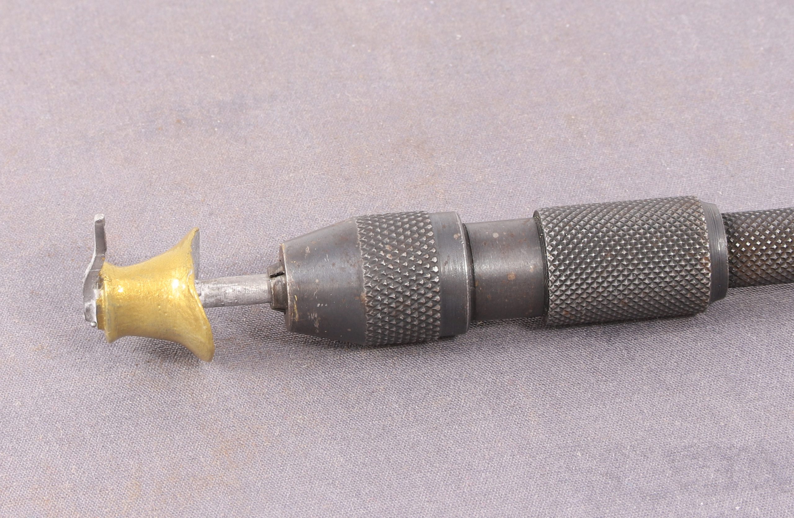
I have done further trials with my Vallejo Old Gold paint mixed 2/3 -1/3 with Vallejo Natural Steel then let down for spraying with Johnsons Klear.
In the first two photos I used the same brass safety valve cover as a comparison piece but realised after taking the photos that the brass had tarnished slightly in the intervening time since I did the last comparison.
I used an image editor (Picasa 3) to add some contrast to the same image.
Then I took another photo after polishing up the brass valve cover again so the comparison is more like for like than the first photo.
And again with a some contrast added
Brass Paint Comparision
I have reached the conclusion that it is possible with good preparation of the whitemetal casting to make a decent fist of painting it with brass paint as long as there is no actual brass in close proximity to allow a direct comparison. I thought that I would pain the dome too to see what a difference a bigger subject made and while it looks okay to use it in practice I would need to fill some holes in the rear of the casting that you cannot see in the images.
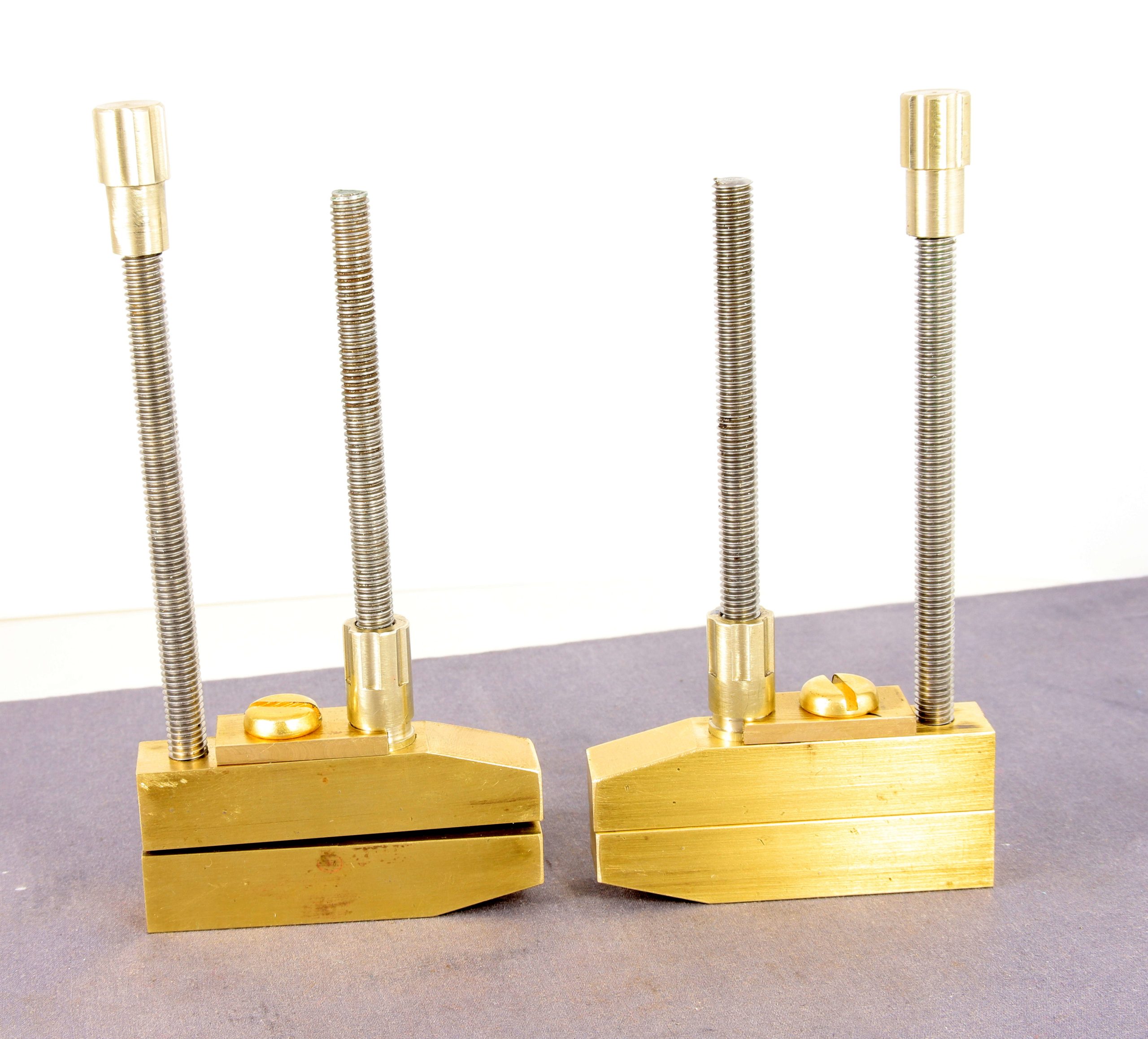
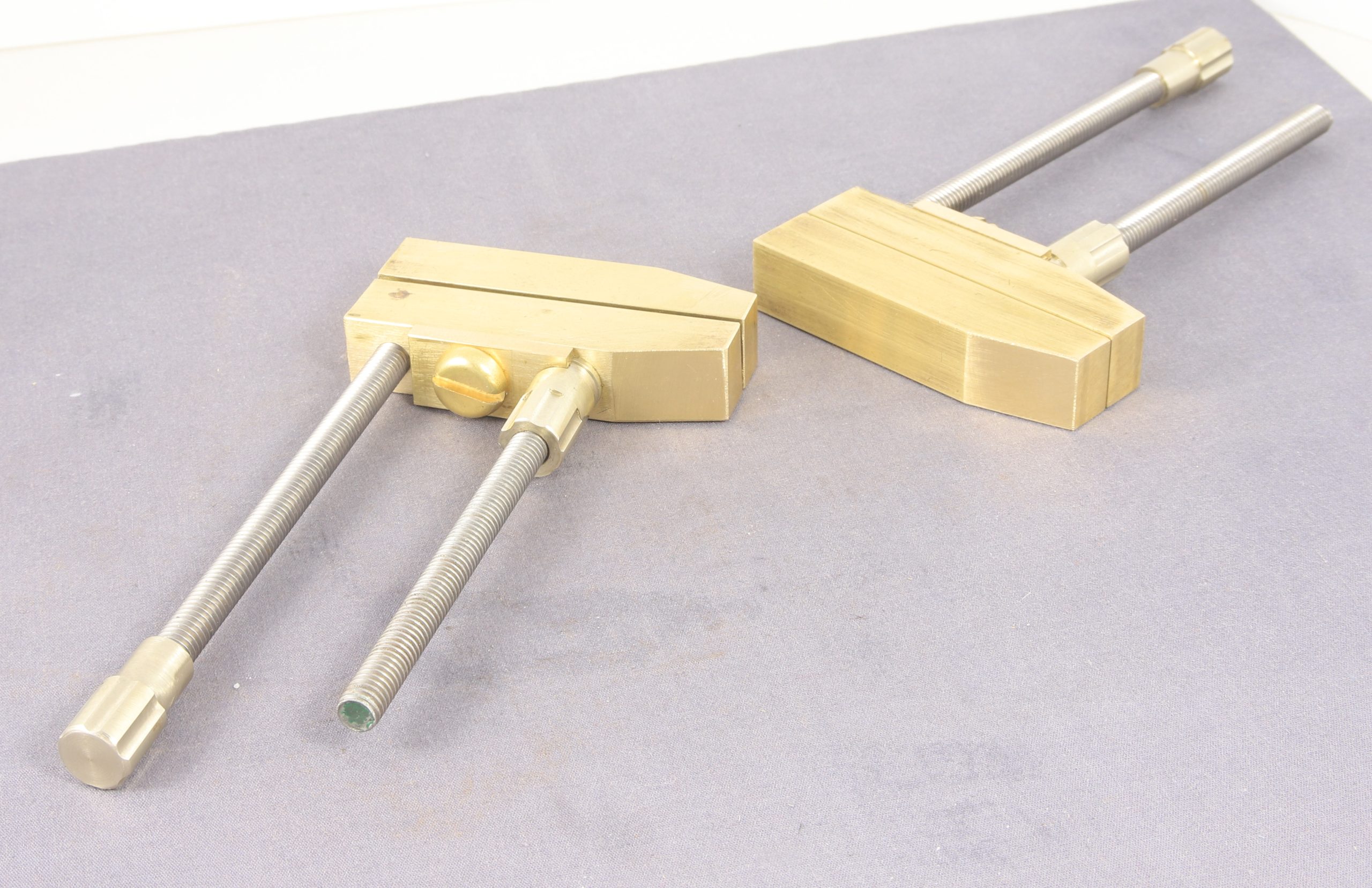
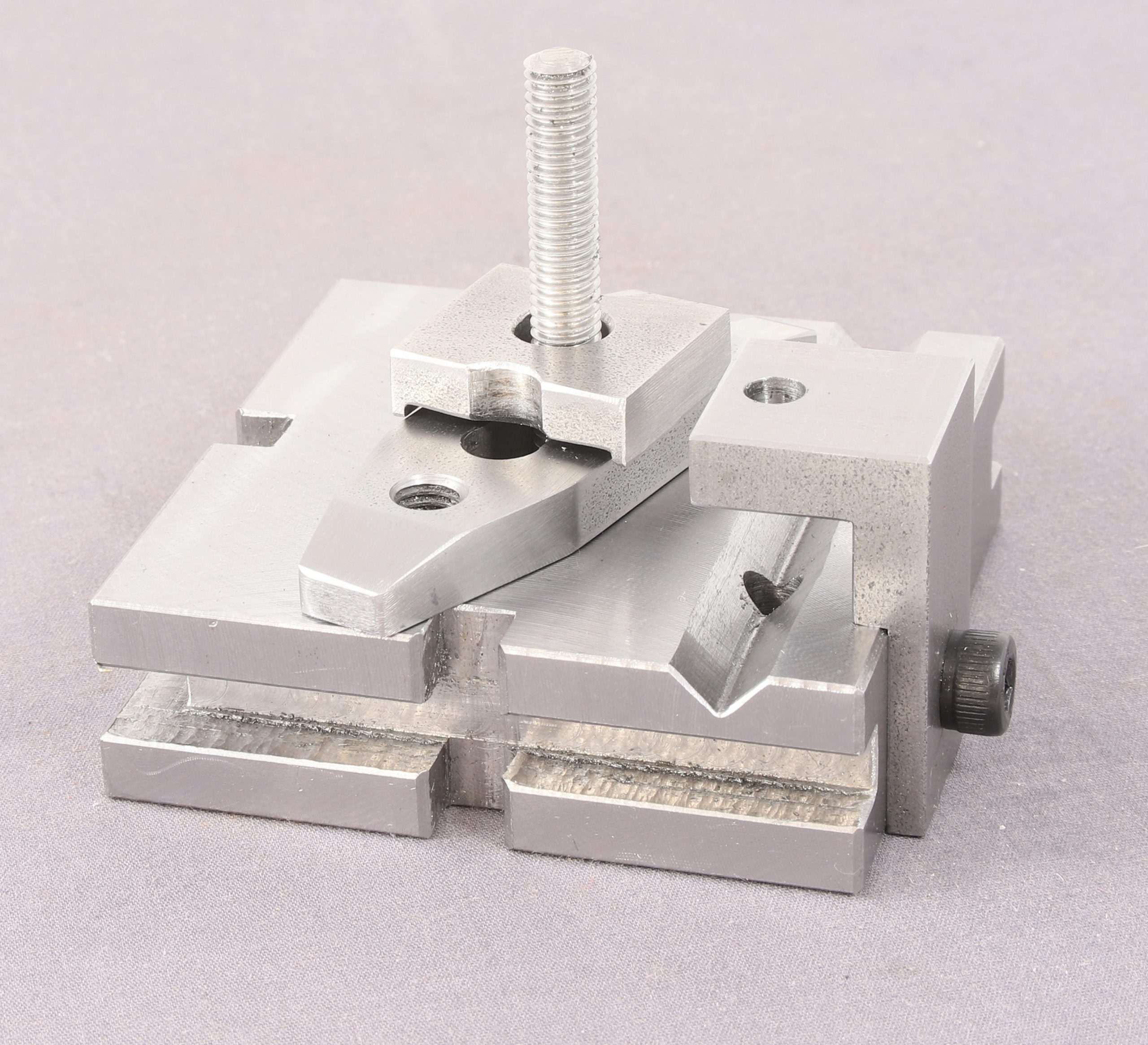
Back in 2023 when I was restoring the Moore And Wright Scribing Block there was a discussion on one of the forums which went along the lines of “you cannot have too many toolmakers or engineers clamps” At the time I had 3 sets that were cheapo imports. Since then I have added another single 2″ Eclipse example to the collection but I was also thinking about a pair that could be used for holding parts for soldering without going rusty.
I happened to have a length of 1/2″ square brass bar that I’d had for a number of years without having a use for it. A quick measure up worked out that I could get two pairs of jaws from it so in the intervening 3 years I have been slowly building a pair. I made the screws from stainless M6 threaded rod and the knobs and nuts were made from 10mm nickel bar.
They have been substantially made for quite some time and really only needed the angles putting on the jaws and some way of retaining the nuts in the absence of having any spring steel. In the end I milled some flat brass bar to fit around a slot cut in the lower section of the nut.
Shop Made Brass Toolmaker’s Clamps
Now all that remains is to loctite the knobs on he ends of the threaded rod and put some on the bottom of the threaded rod where it screws into the front lower jaw.
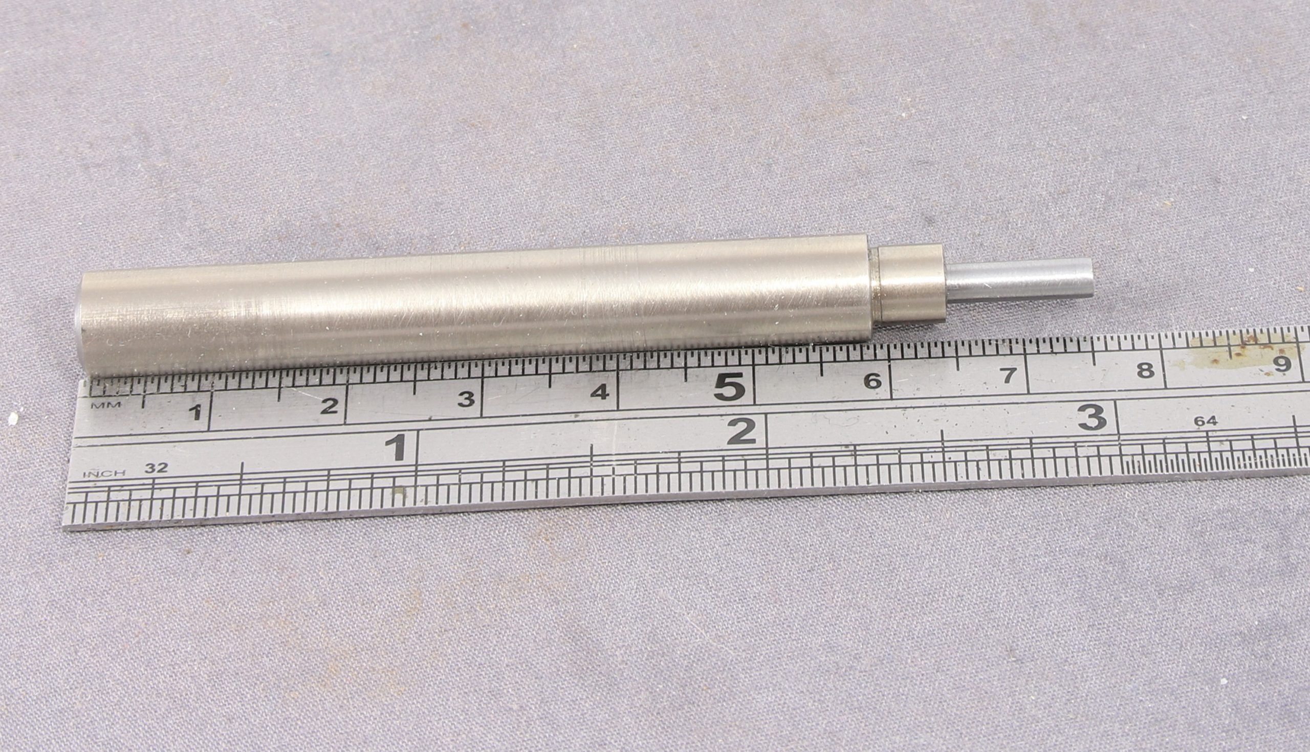
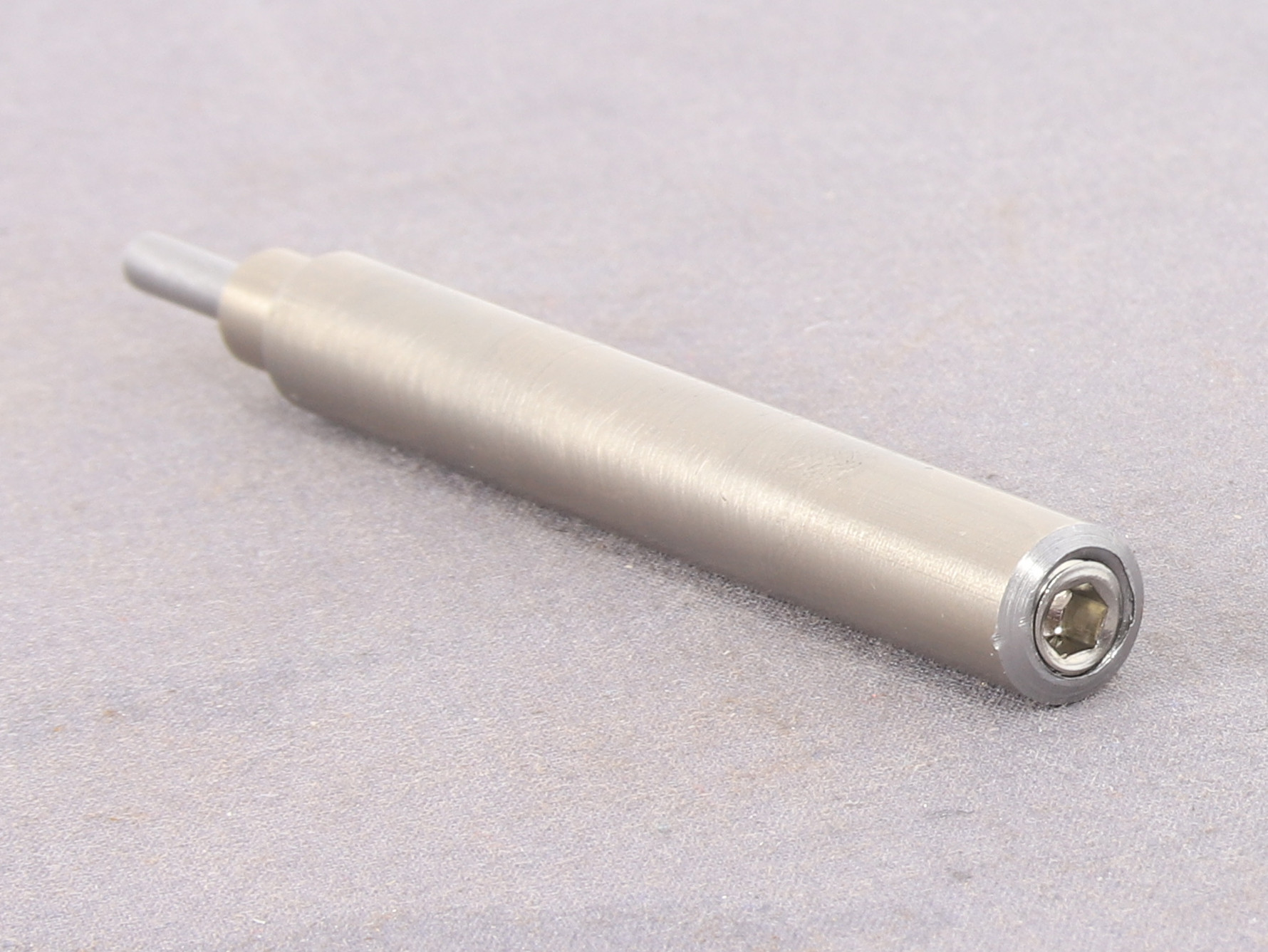
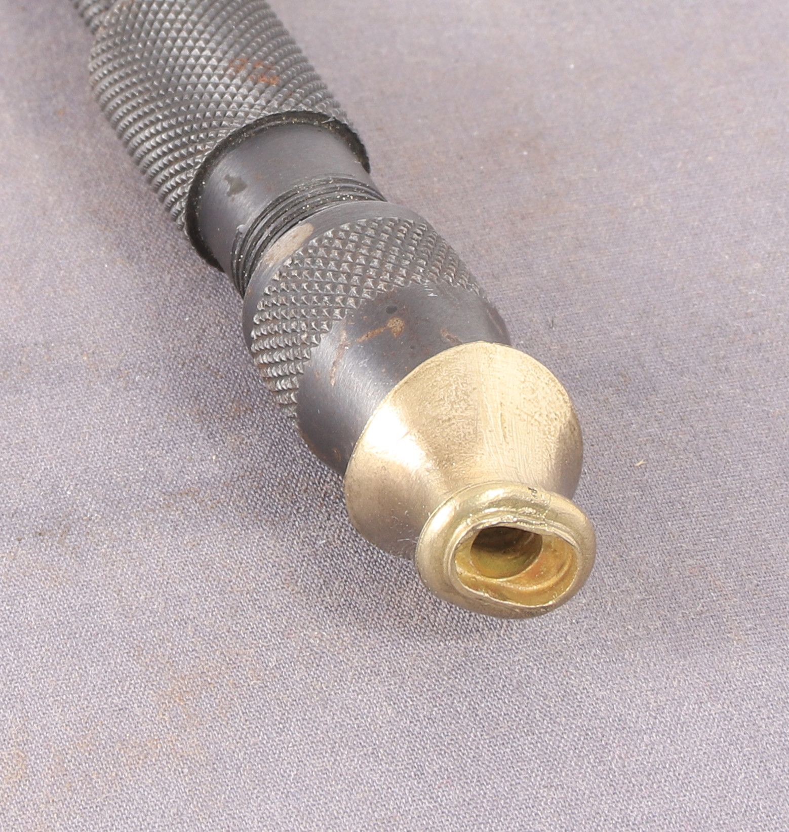
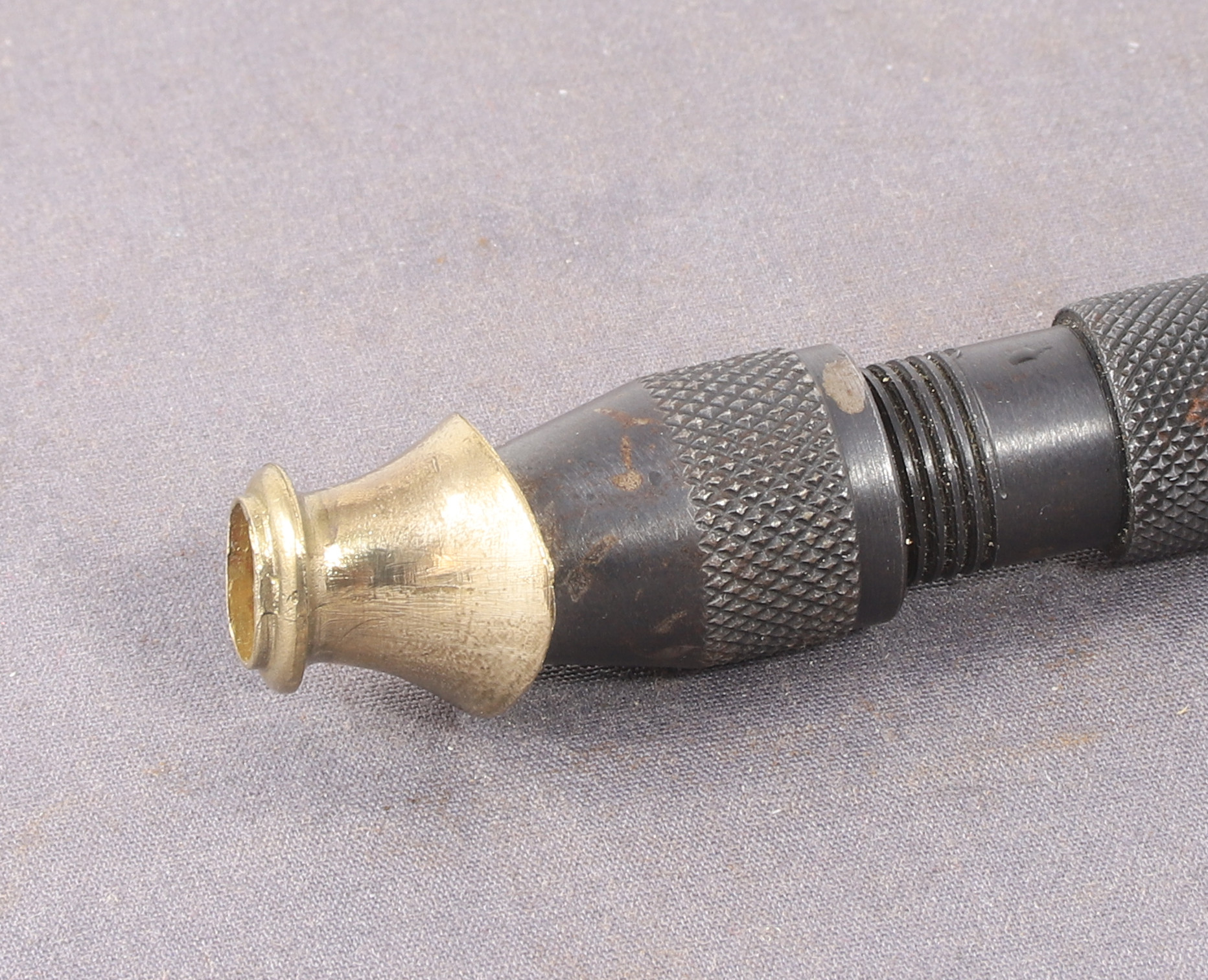
Since buying and later modifying a tap follower back in 2023 I have used it many times and I wouldn’t be without it. However one thing about it is a bit of a pain, or perhaps I am just bit lazy. That is swapping the piston over end for end depending on whether my tap has a point or a dimple.
As a rule of thumb most of the bigger size taps have dimples whereas the smaller sized ones tend to have a point or at least a tapered end.
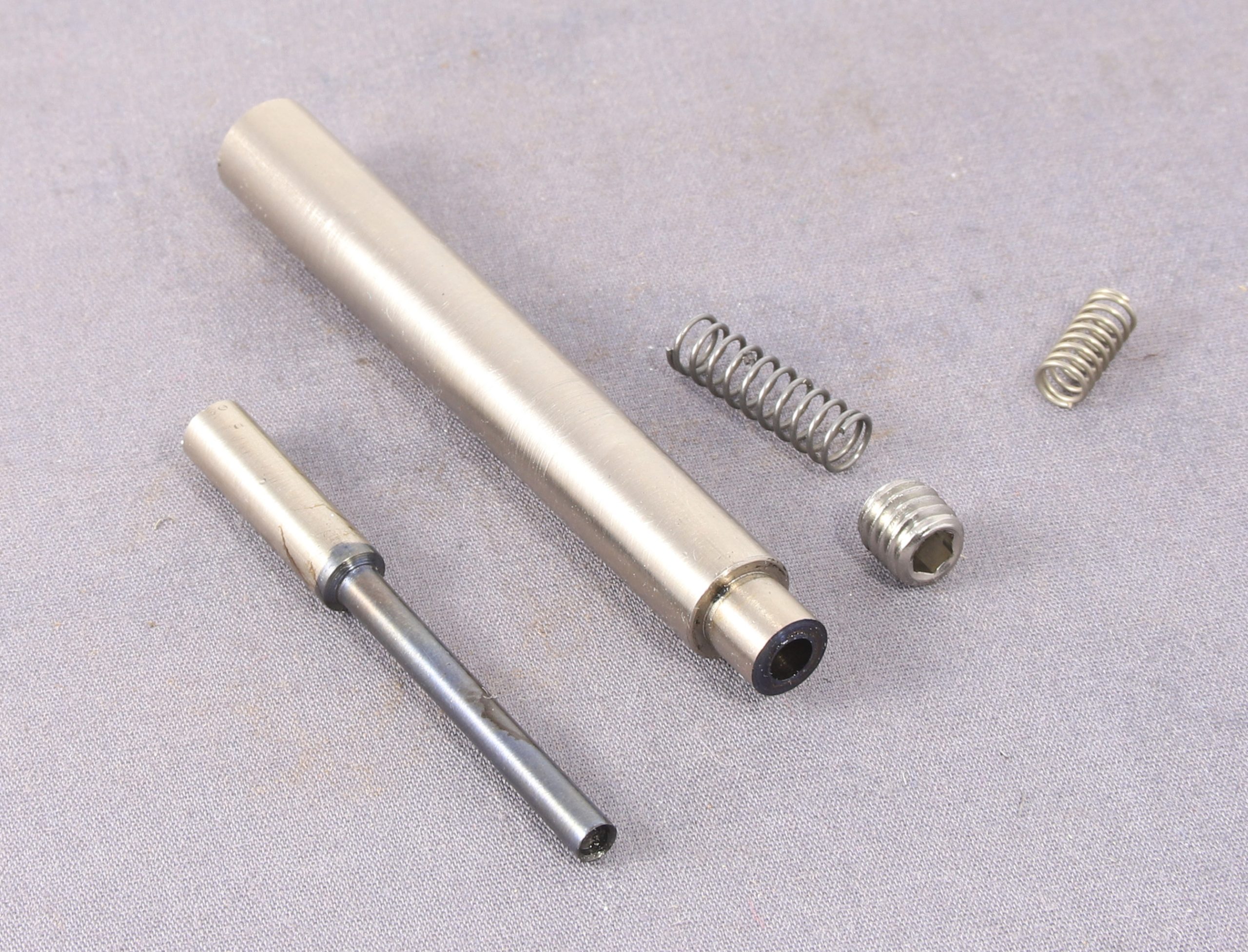
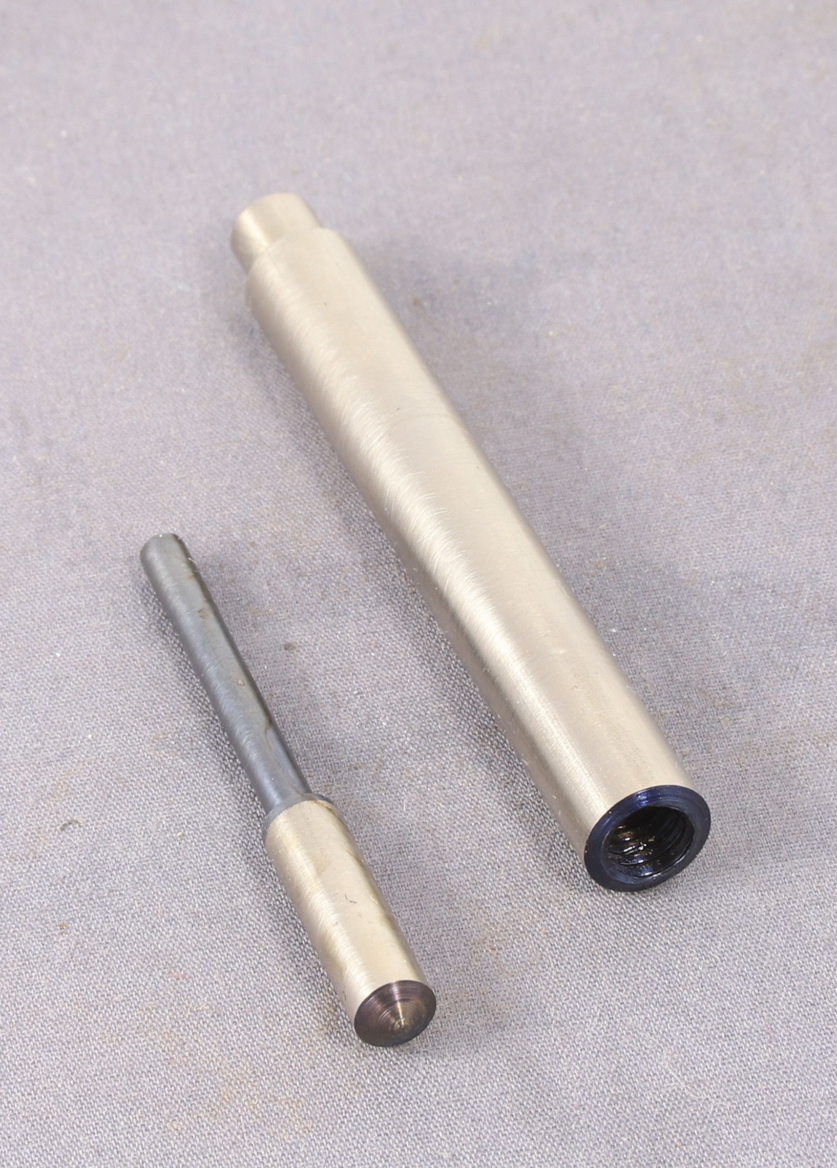
To get around this I dedided to make a second smaller tap follower with lighter springing that could be dedicated to the smaller taps that I seem to use a lot.
I decided to make it from a couple of pieces of rod recovered from a printer drum unit. The main barrel being 8mm in diameter which will fit in all my Jacobs drill chucks without issue and the piiston end made from some 5mm rod, again from the drum unit.
Springs from my spares box and an M6 grub screw and away I went.
I chose M6 because the tapping size is 5mm which meant that my piston could be a 5mm rod with the end turned down to pass through a smaller hole in the end. So it was a case of drilling the main body 4.8 mm and then reaming to 5mm with a 2.9mm hole in the other end reamed to 3mm. Sadly all didn’t go as planned because in a moment of inattention I broke my 3mm reamer in the hole. After trying a couple of pins to knock it out and a 3mm carbide end mill I turned a little off the length until I exposed the broren end of the reamer then using my vice as a press I managed to push it part way through. Then I found in my bits box a short length of rod with a smaller stub which fitted in the 3mm hole. Using this as a drift I managed to push the reamer a little further in, then I turned the small stub end a little longer and repeated the process it took turning 3 more sections down before the reamer popped out. Then I ran another 3mm end mill through the hole to tidy it up and get it concentric before finally turning the small end of the piston to be a tight but sliding fit in the hole.
A fun little project that had I not broken the reamer would have only taken an hour or so. I’m sure that it will see much use in the future
Having spent eight days making the jig it only took about 20 minutes to actually do the job.
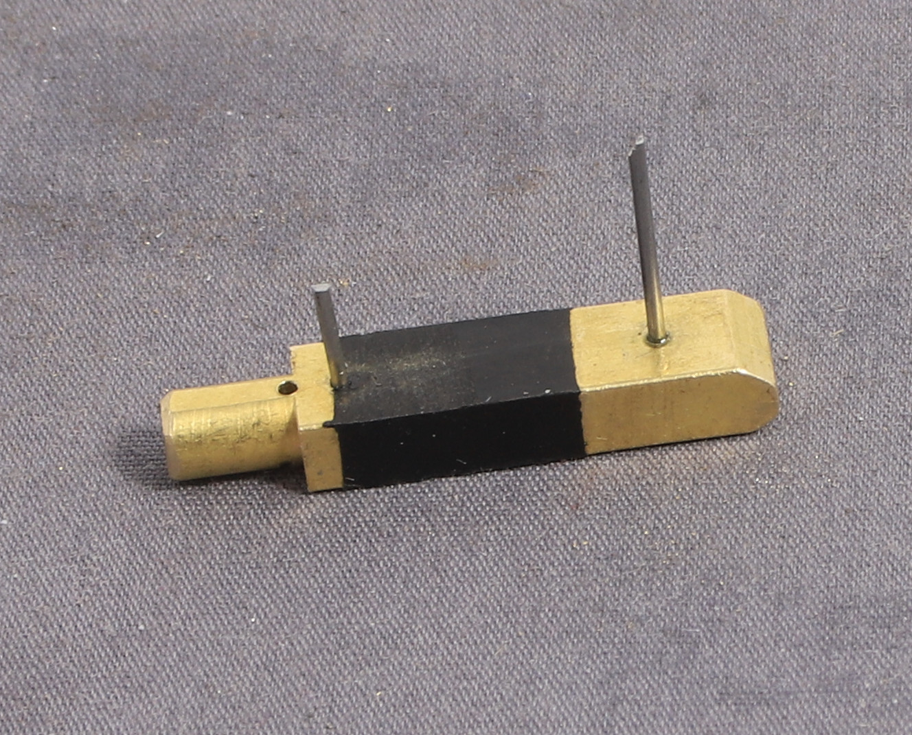
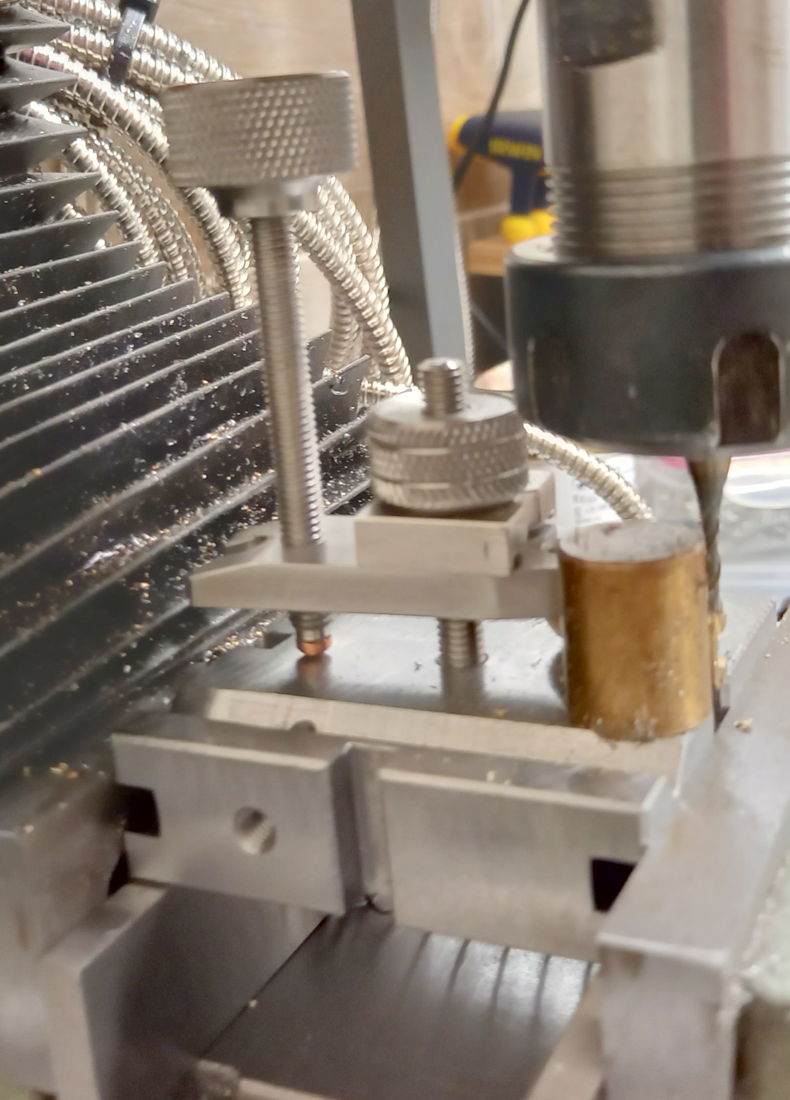
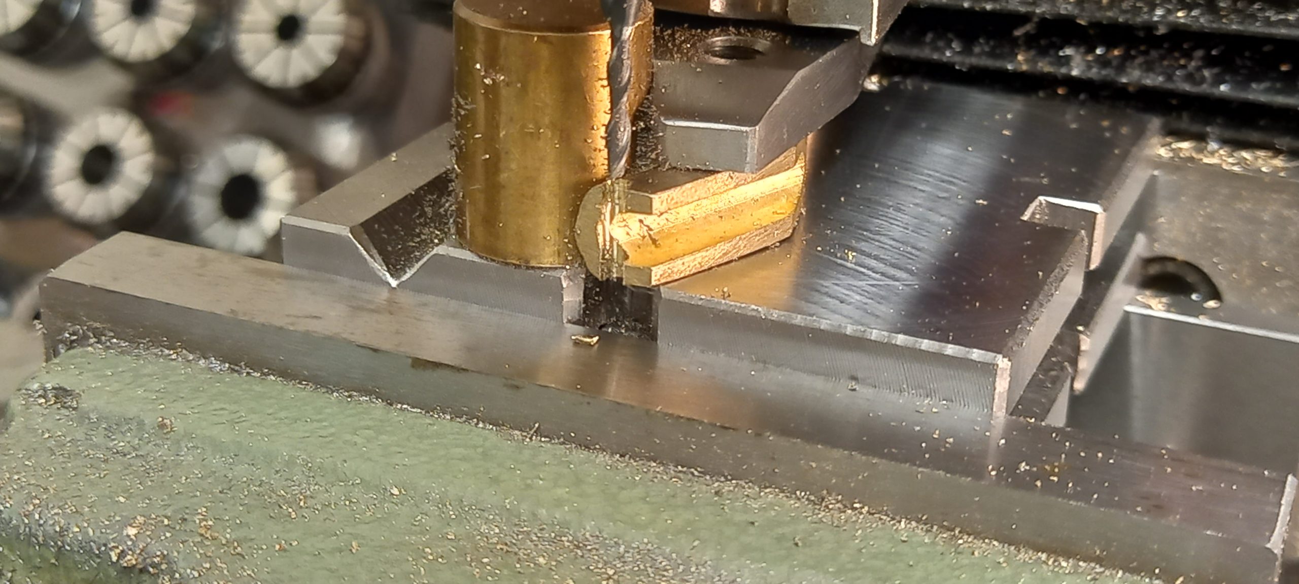
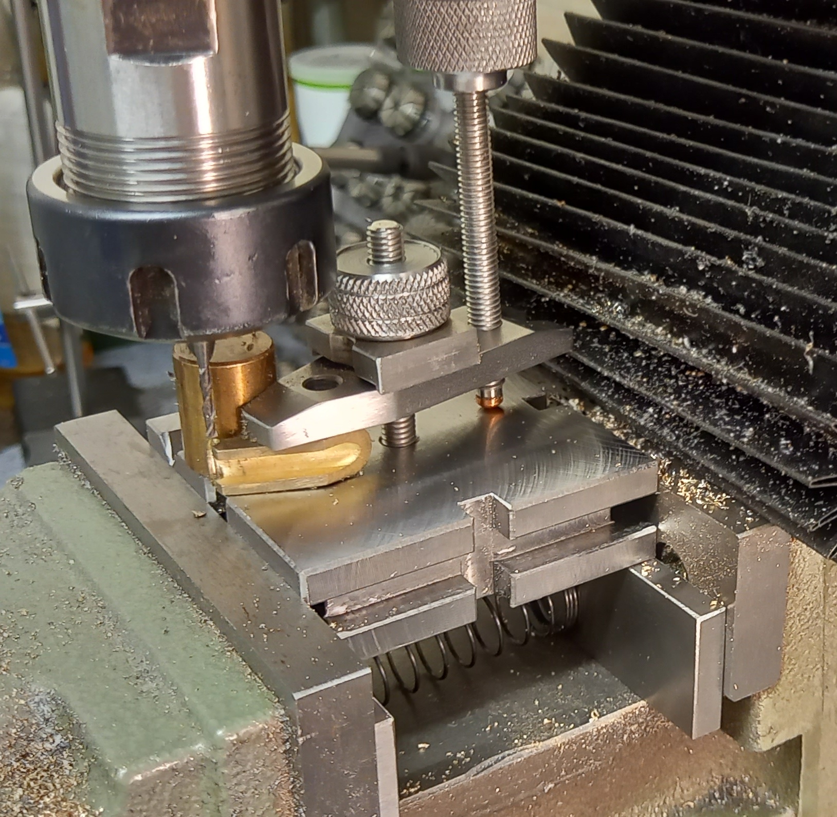
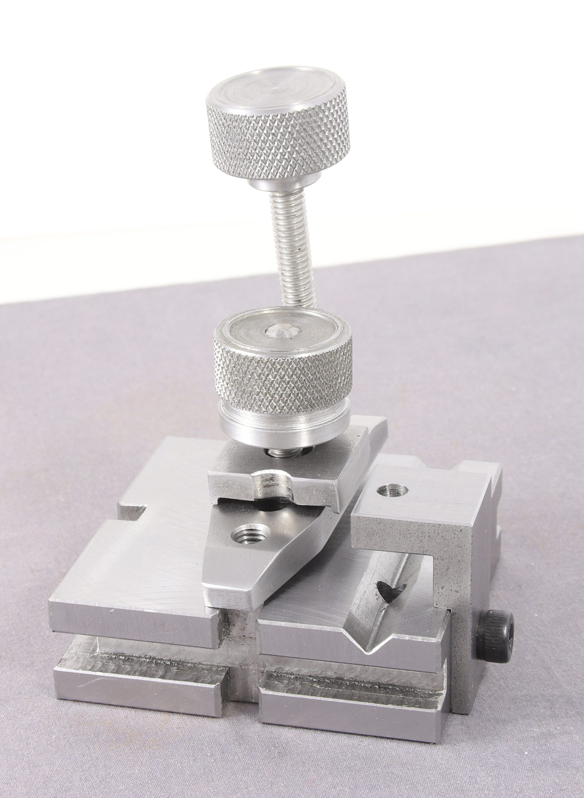
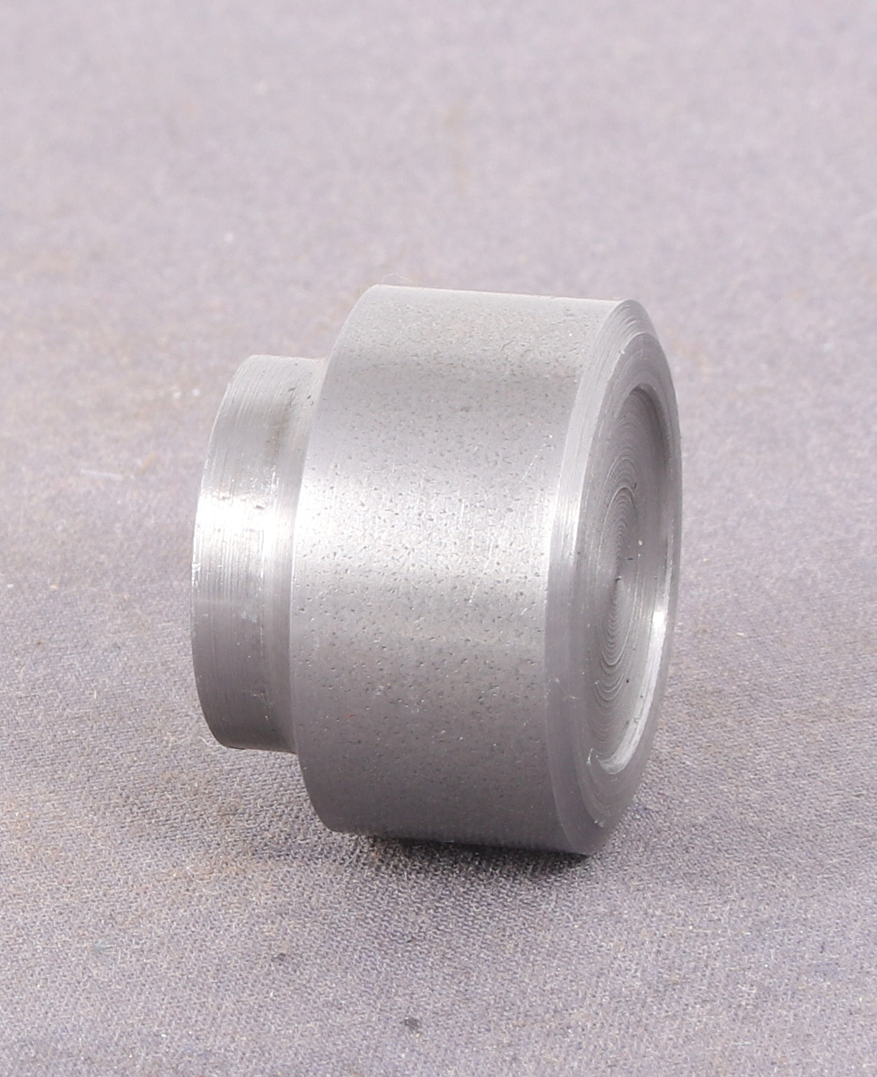
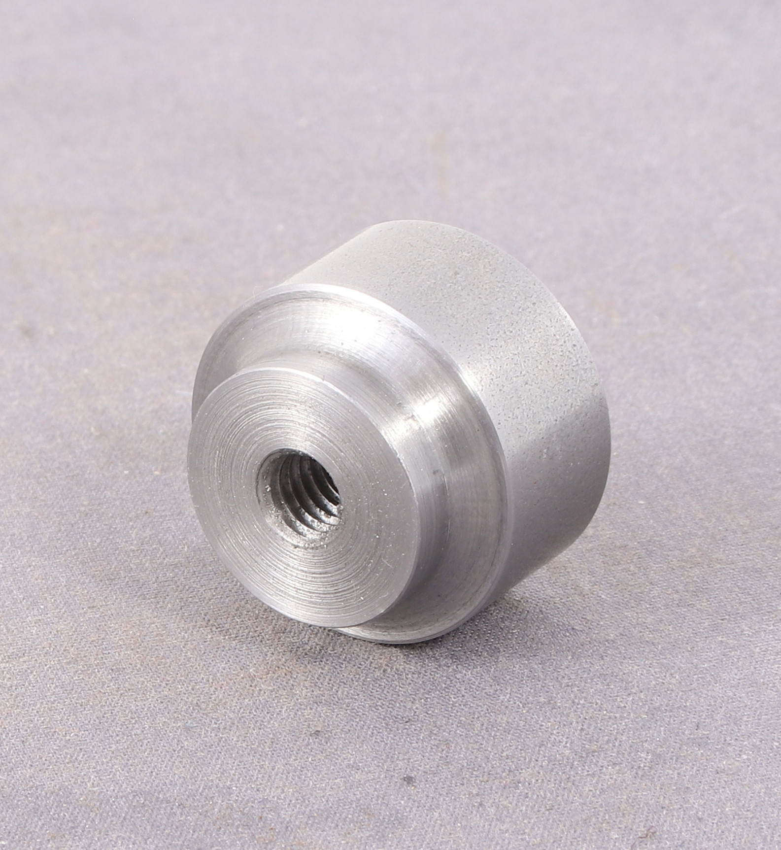
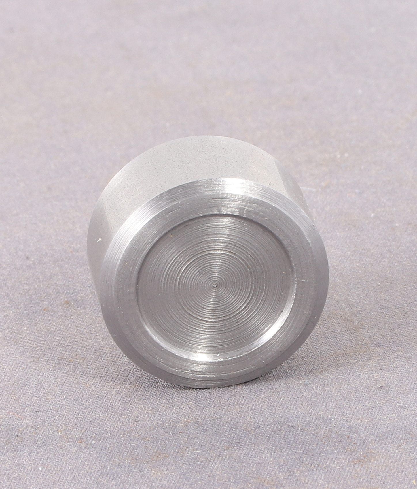
Yesterday morning, I decided to see if I could salvage the damaged original nut that I made for the finger plate. It’s a good job I did because the nut that I had made to replace the damaged one was too big to allow my 2mm milling cutter to get close enough to the job without catching on the nut. So I dug out the now smaller diameter original and that allowed enough clearance to get the job done.
The brass cylinder that you can see in the photos is actually a strong magnet inside a brass sleeve which came with my RSU but I have never used it before. In this instance it’s being used as a reference stop so that I can easily locate the second steam pipe in the same place for machining.
I used a parallel to align the bottom face of the casting with the edge of the finger plate so that I could mill/drill into the slot.
I am pleased to say that it did the job exactly as it said on the tin so to speak.
It also occurred to me this morning that having replaced the 1/4-40 tpi and 1/4 UNC threaded parts with M6 I can also use standard M6 hardware in the finger plate if I need even more clearance at any point in the future.
As a complete aside, and those with a bandsaw look away and start sniggering now.
Despite attaining poor results at accuracy with a file, I have long prided myself on my ability to follow a line with a saw.
This morning I made a 140mm (5-1/2in) cut in a piece of 10mm thick steel plate with a hacksaw to within 0.5mm end to end. Which I will take as a win – That said it did take me an hour (I had a coffee in between two sessions with the saw) and apparently it’s character building. I feel that I must have a mighty fine character after that effort.
The other piece (this is the offcut) is destined to be a fixture plate for the mill at some point.
A couple of things worth mentioning about Hemingway kits and my experiences during the build.
Most of the Hemingway kits have all the dimensions in imperial although where they supply hardware it’s metric (the cap screw which holds the drill guide support is M5 for example). Although I have a set of imperial reamers, I don’t have many imperial taps and dies (you can count both on one hand I think) so I converted all the screw threads to metric. I also used M6 threaded rod as I had it in stock, rather than the two different threads quoted for the pivot screw (1/4 x 40tpi and 1/4 BSW) and the 1/4 x 40 tpi for the jack screw.
The second thing, which isn’t about the kit per se, but my experience or rather inexperience in milling grooves in steel. I was using 6mm carbide end mill in place of the quoted 1/4″ slot drill and proceeding cautiously. After a bit I plucked up the courage to feed a bit faster and what a difference it made to the cutting.
I know that carbide lathe tooling seems to like higher speeds and faster feeds to find the sweet spot where it cuts well and leaves a nice finish. But I hadn’t translated that into mill tooling, as most of my experience milling to date has been with HSS tooling.
I say finished for now because I am undecided whether to blue any of the parts and I am leaving the drill bushings undrilled until I actually need them then I will ill to the size that I need at the time.
I was able to get four blanks from the length of rod provided with a small offcut of about 8mm left.
Almost the last parts to be made are the knob for the Jack screw and the nut for the rocker plate.
Sadly I ended up making these twice because I had planned to mill scallops into the edges in place of knurling but the nut unscrewed itself from the mandrel and the cutter chewed it up. So I remade them and knurled them. The knurling came out better than I had hoped so I am pleased with that.
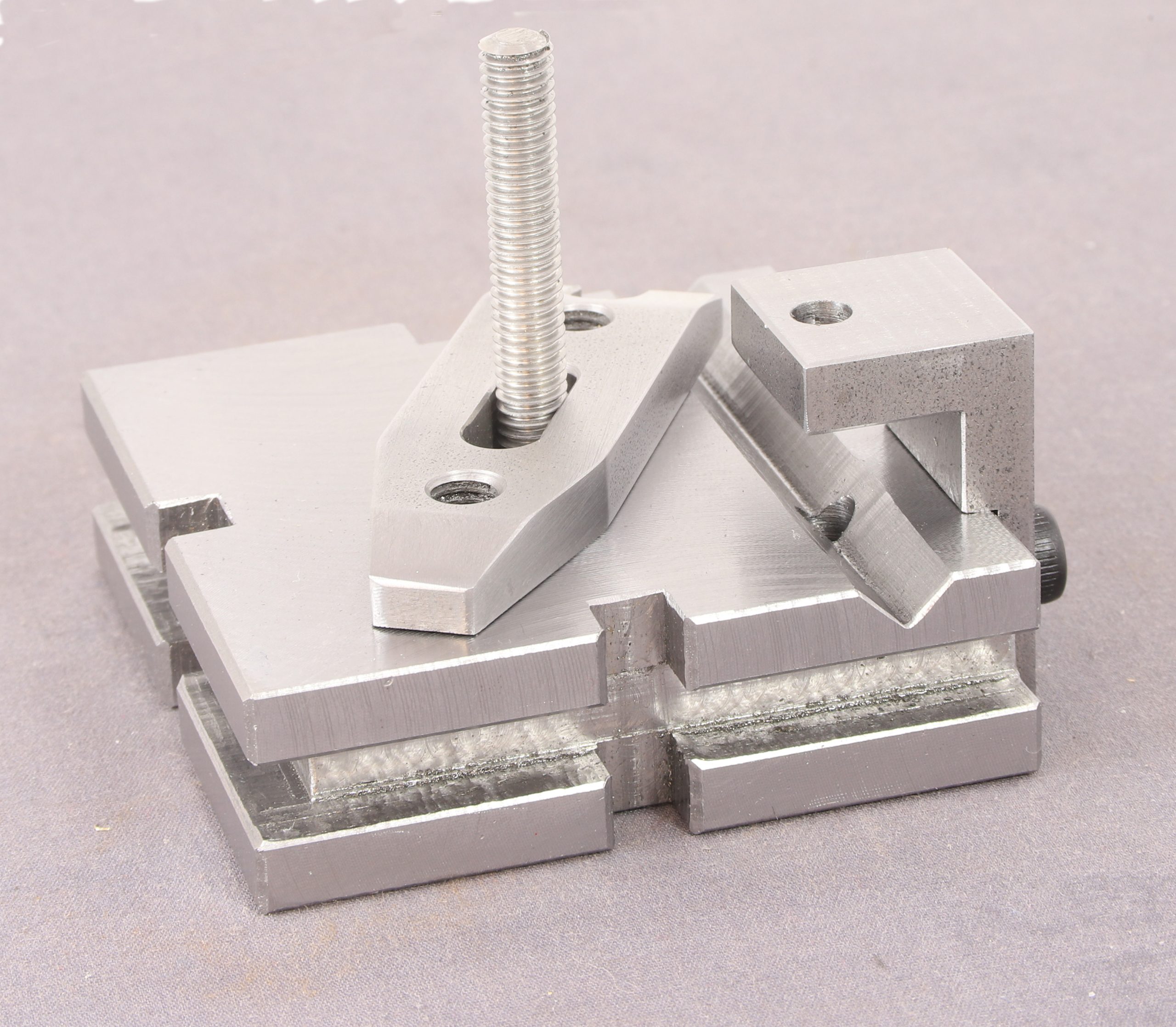
Here we have the assembled tool with the knob and nut in place I made the nut a little bigger than the plan called for so I have something to grab hold of.
I also ended up with a spare plain knob which will go in the spares box.
Next up are the very last bits to make which are the drill guide bushings. These are turned from the provided silver steel rod and the idea is that once drilled to the appropriate size you harden them to prevent wear over time.
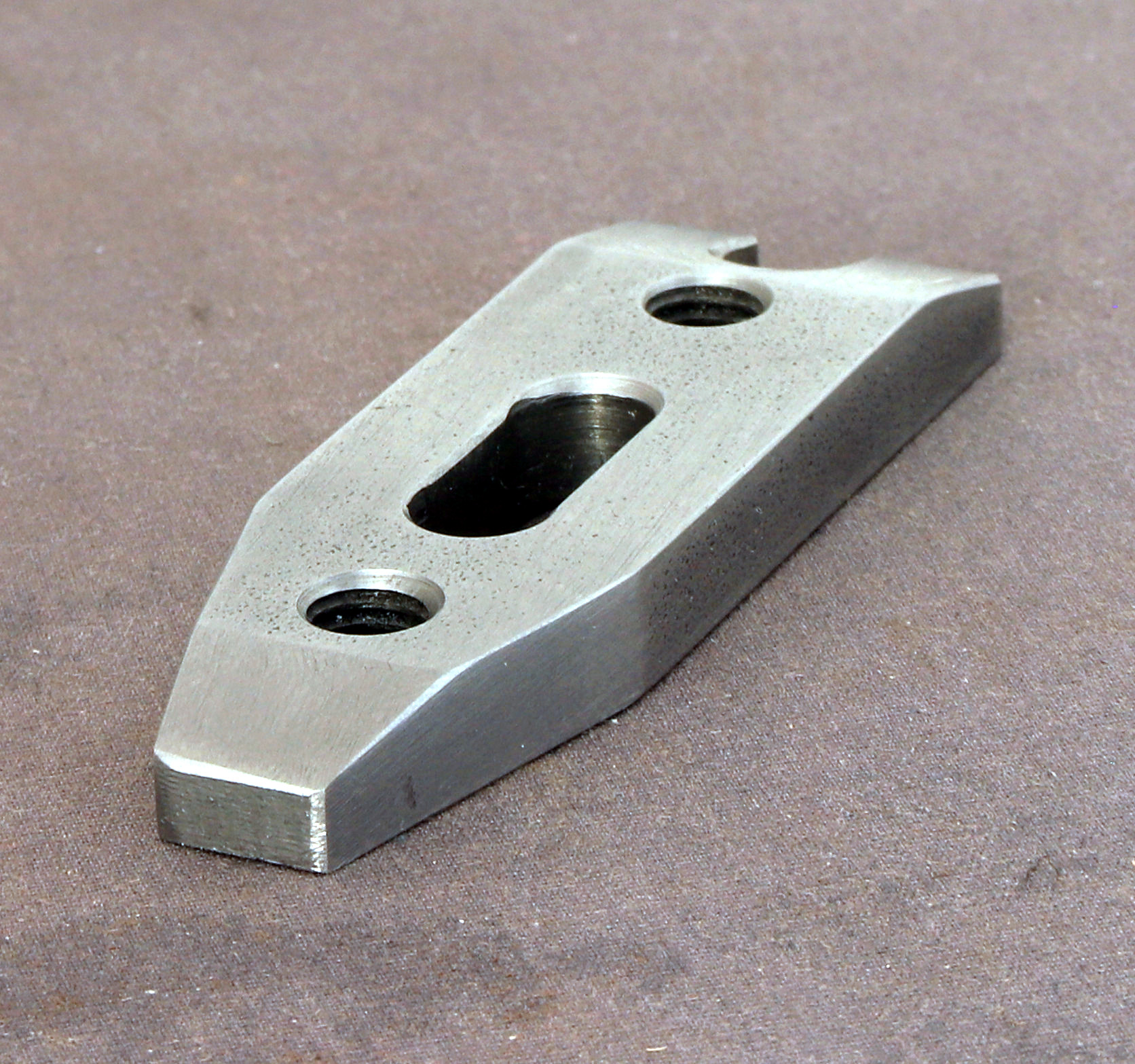
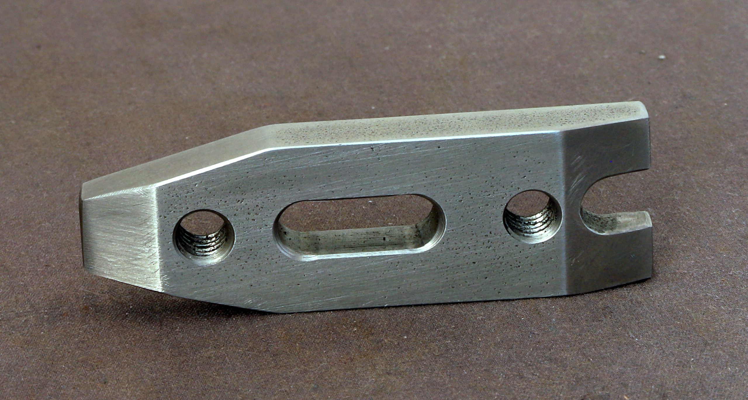
The next part to make was the ‘finger’ which grips the parts to be machined or drilled.
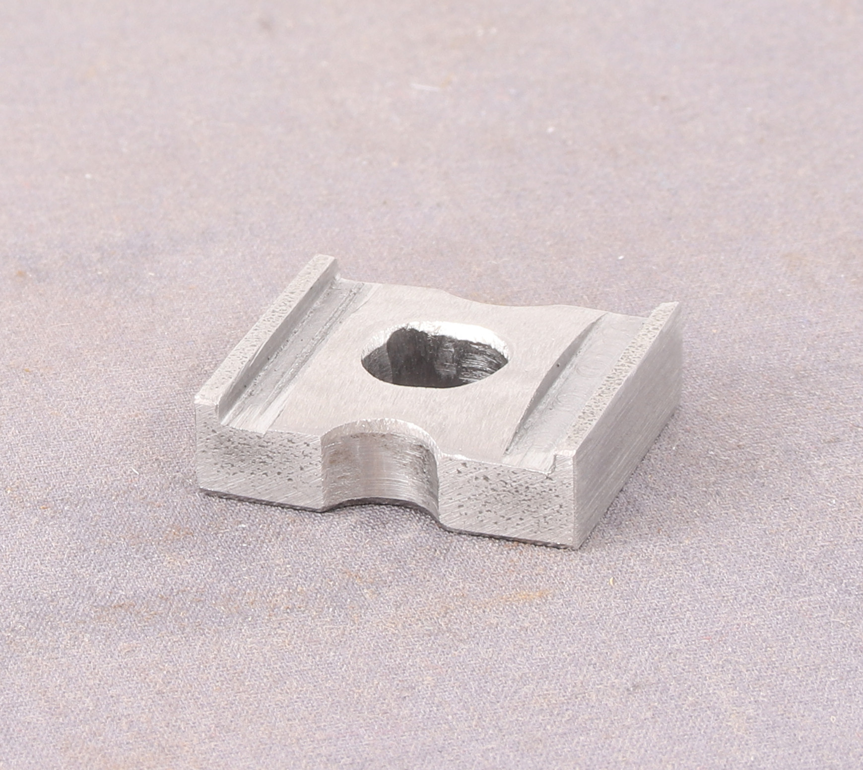
Followed by the Rocker plate
All that remain are the knob for the Jack Screw and the ‘Nut’ to tighten the rocker plate onto the finger. Plus assorted drill bushings sizes yet to be determined.
A friend (Richard) were discussing painting whitemetal safety valve covers with ‘brass’ paint. I had idly mentioned to Richard to polish the metallic paint after it dries with either a cotton bud or kitchen paper. It was during this discussion that it occured to me to use a buffing wheel in a mini drill instead.
I dug out a whitemetal safety valve casting from my H2/J79 kit and after buffing up the casting I brush painted some Vallejo Old Gold onto it. and then when dried overnight buffed it with the mini drill. Getting decent photos of it proved quite a pain but I got something.
Then it occured to me to to add a coat of Johnsons Klear
I still wasn’t too happy with the result but at this point I thought that it was down to the finish of the casting so instead of using a buffing wheel I used a wire cup brush in the mini drill. At the same time I thought it prudent to also polish up a brass casting so I could have a proper comparison the casting in question is a Gladiator example as I had bought a number of them from David to replace the whitemetal casting in a number of ex NER loco kits.
It was at this point that I realised that my Old Gold was not the right colour but I was part way through the next experiment so I ran with it.
My third example is another whitemetal casting this one from my J71 kit and the sequence was was polish the casting with a wire brush then spray rather than brush more Old Gold but this time let down for spraying with Johnsons Klear.
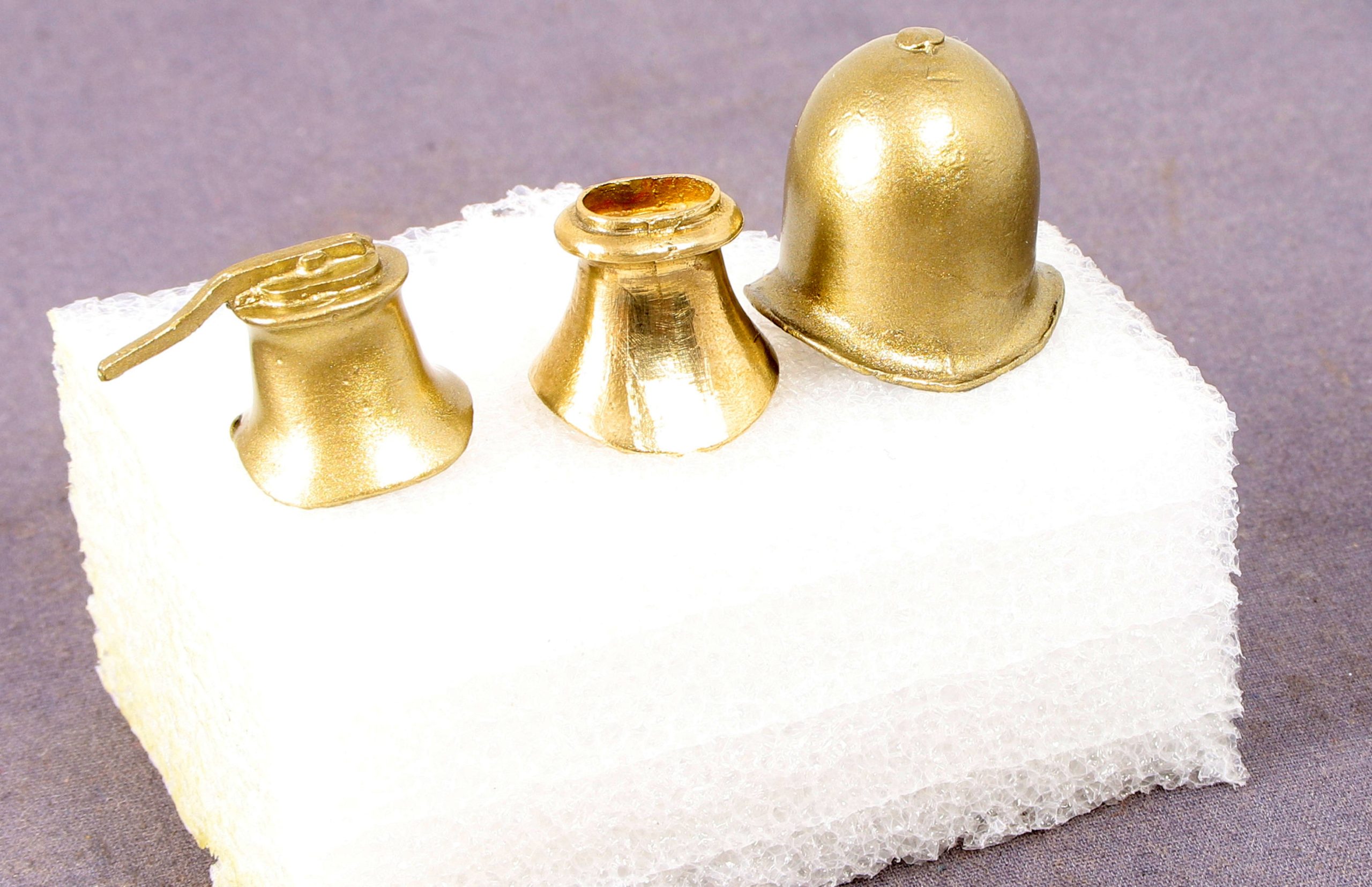
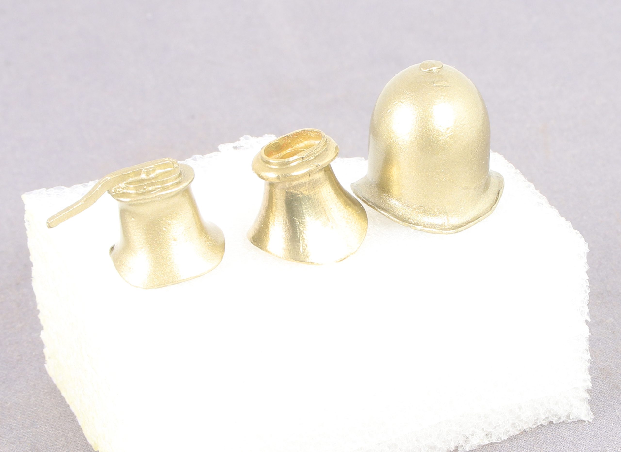
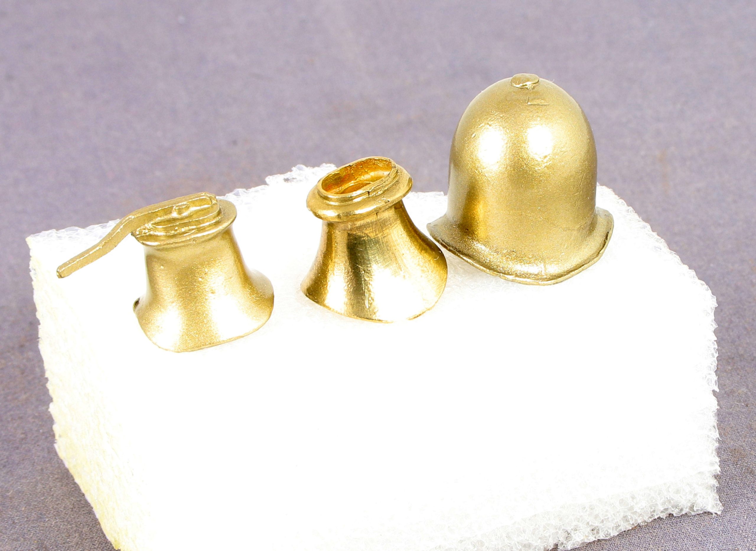
Here are the three together. The polished and sprayed example is by far the best in terms of finish but the colour is wrong when in direct comparison to the actual brass.
I consulted my good lady as to what I might need to add to the old gold to make it more like the brass example and she suggests white or silver to make it paler. I don’t have anymore safety valve castings to hand so I was going to use a dome instead but in the interests of keeping them all similar I elected to stripp the paint off the first expample so that I could polish the casting with the wire brush before trying again with a lighter hopefully more brassey colour. TBC
As an aside I thought perhaps I could cut out the stripping stage by attacking the painted casting with my wire brush in the mini drill. I was really surprised that it didn’t budge it. Despite giving it a good going over all it did was further polish the surface so those who doubt the toughness of modern acrylics take note. Now the casting is soaking in some clean spirit to soften the paint before i have another go.
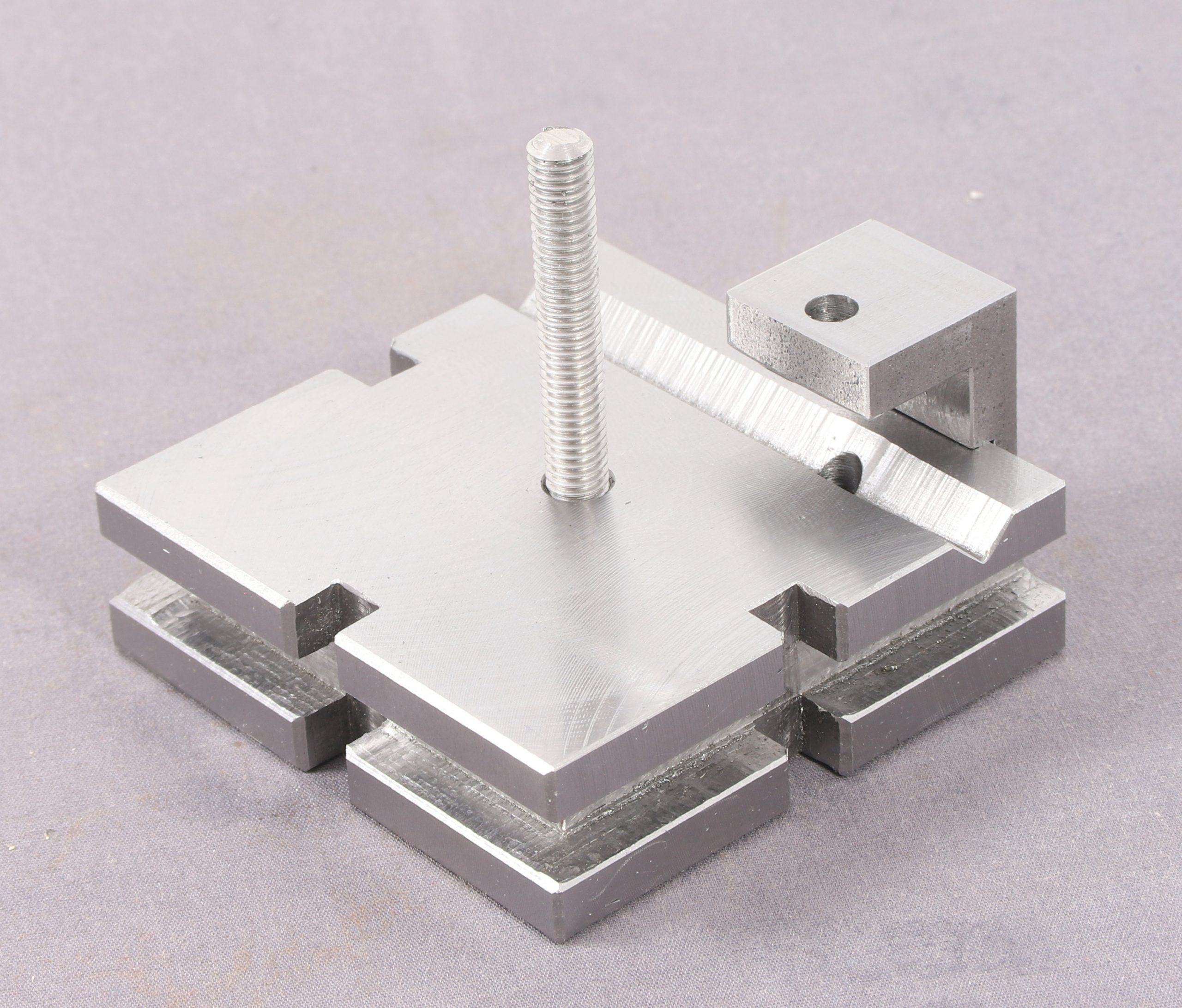
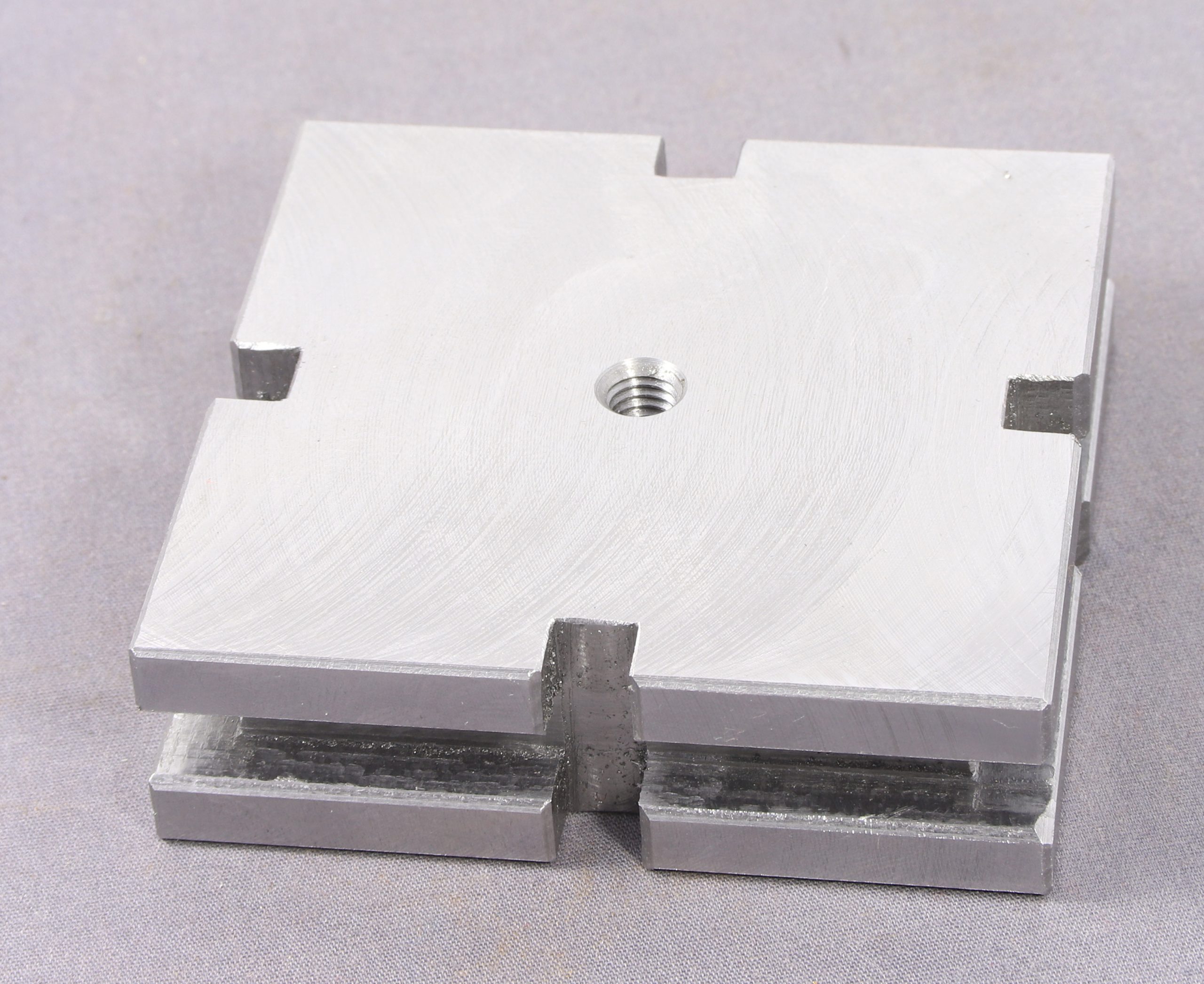
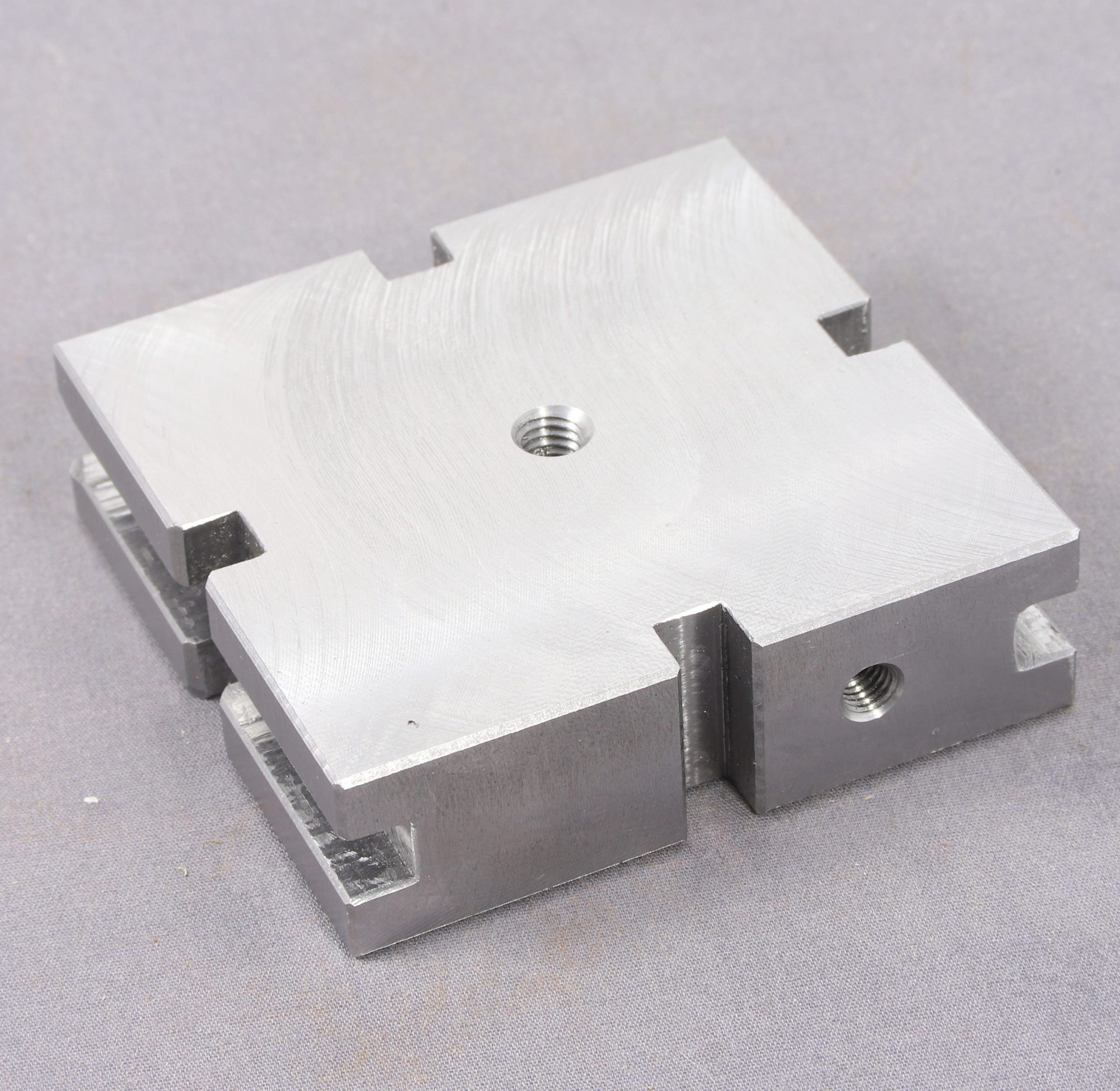
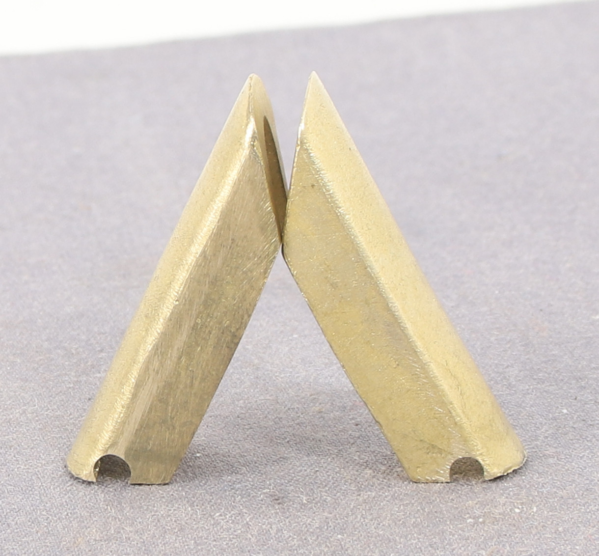
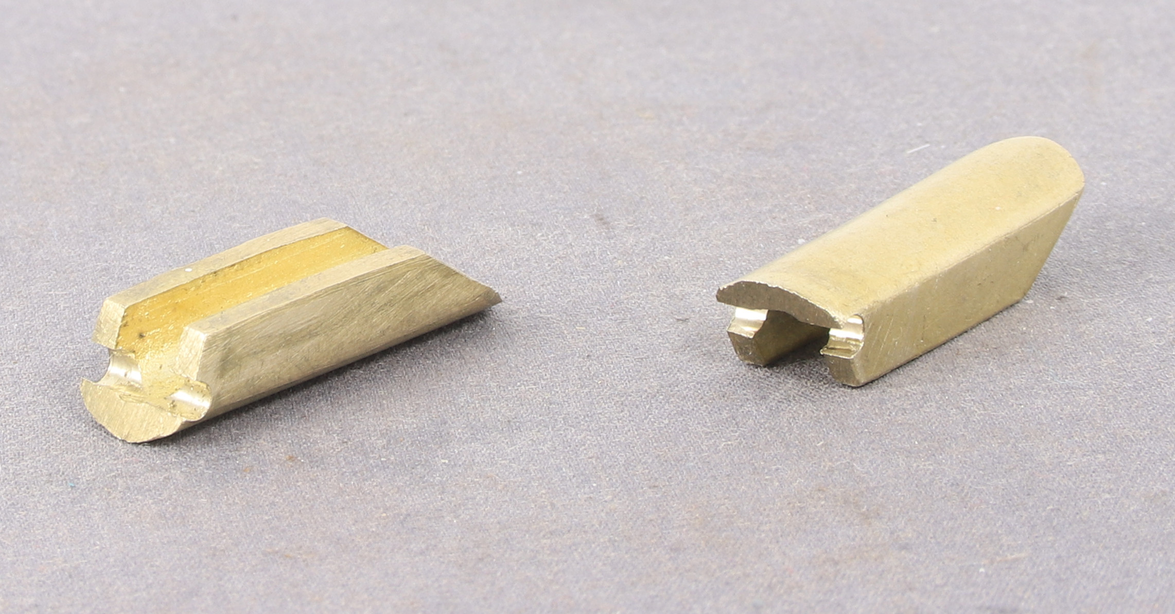
Returning to the 8F after fitting Digital readouts to my Lathe I decided to do more work on the loco body before completing the detailing of the frames. One of the next steps is to drill or mill out the hole in the bottom of the steam pipes adjacent to the smokebox which were apparent on some locos but not all. Mine is to be one of those with the holes.
The next question was how on earth would I hold them to mill/drill them as they are quite an irregular shape.
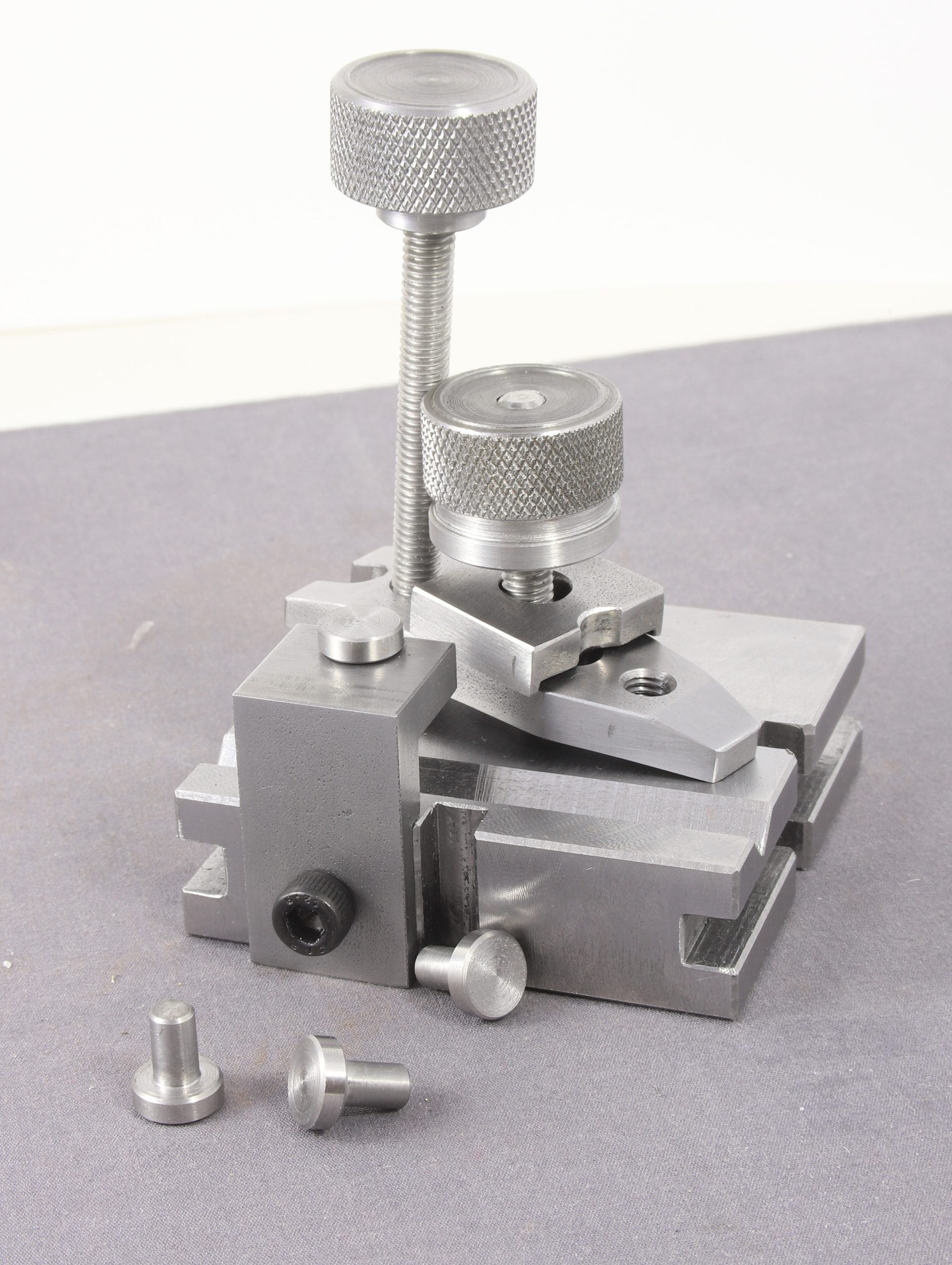
After a bit of deliberation and trying out of angle blocks I remembered that the year before last my son had bought me a couple of Hemingway Toolro0m kits and one of the is a Finger Plate. For those wishing to see it in detail follow this link – https://www.hemingwaykits.com/HK1390
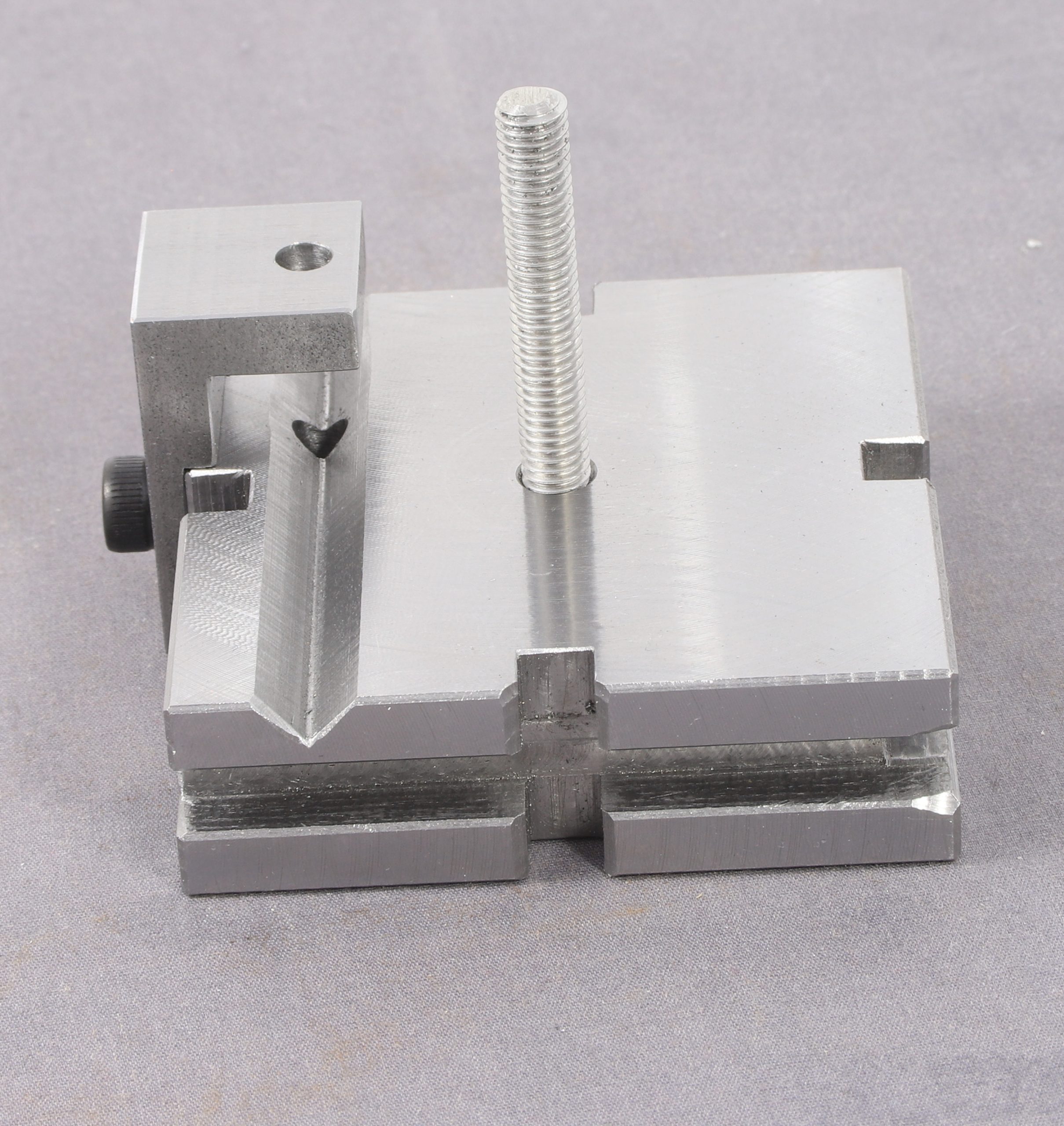
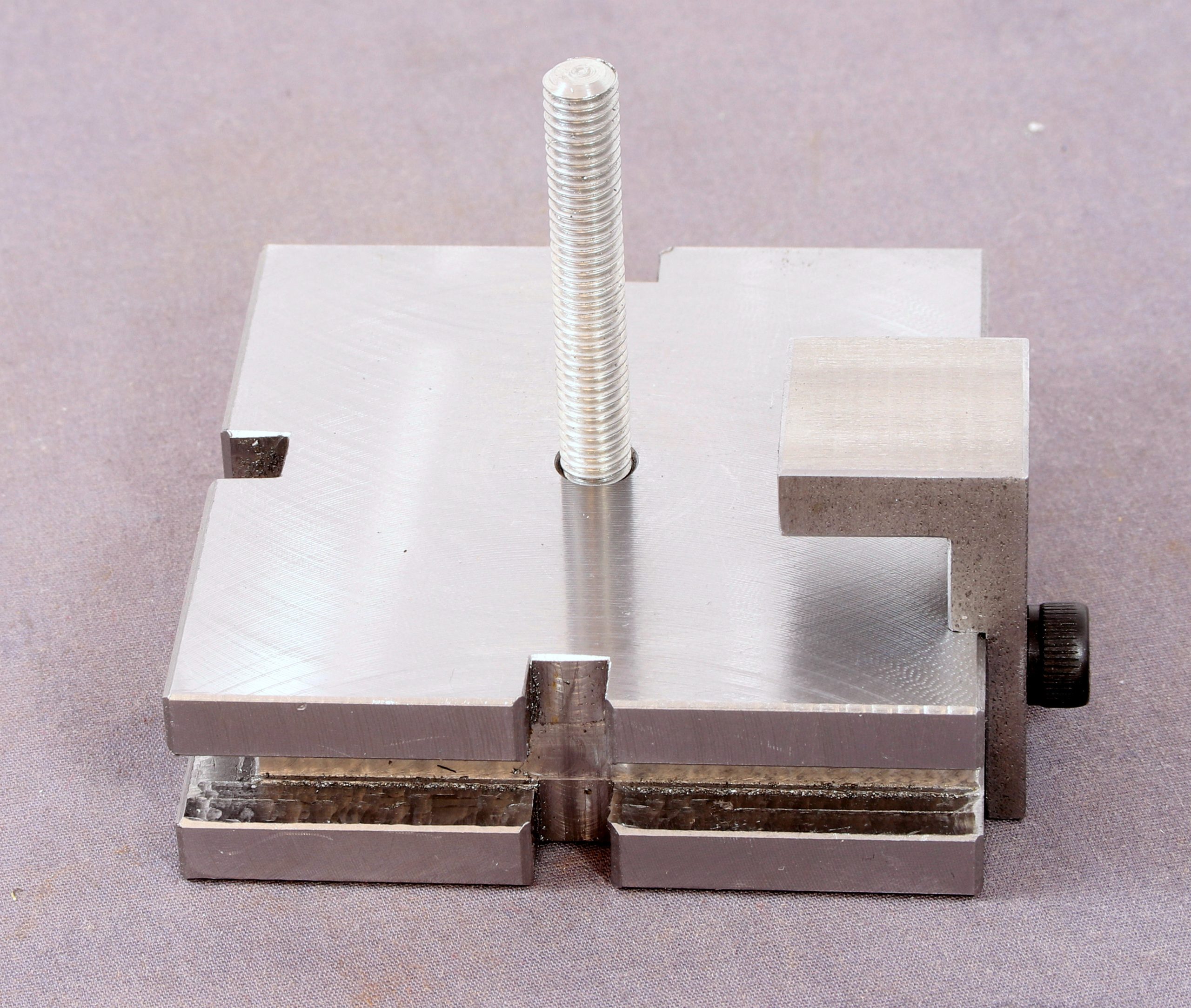
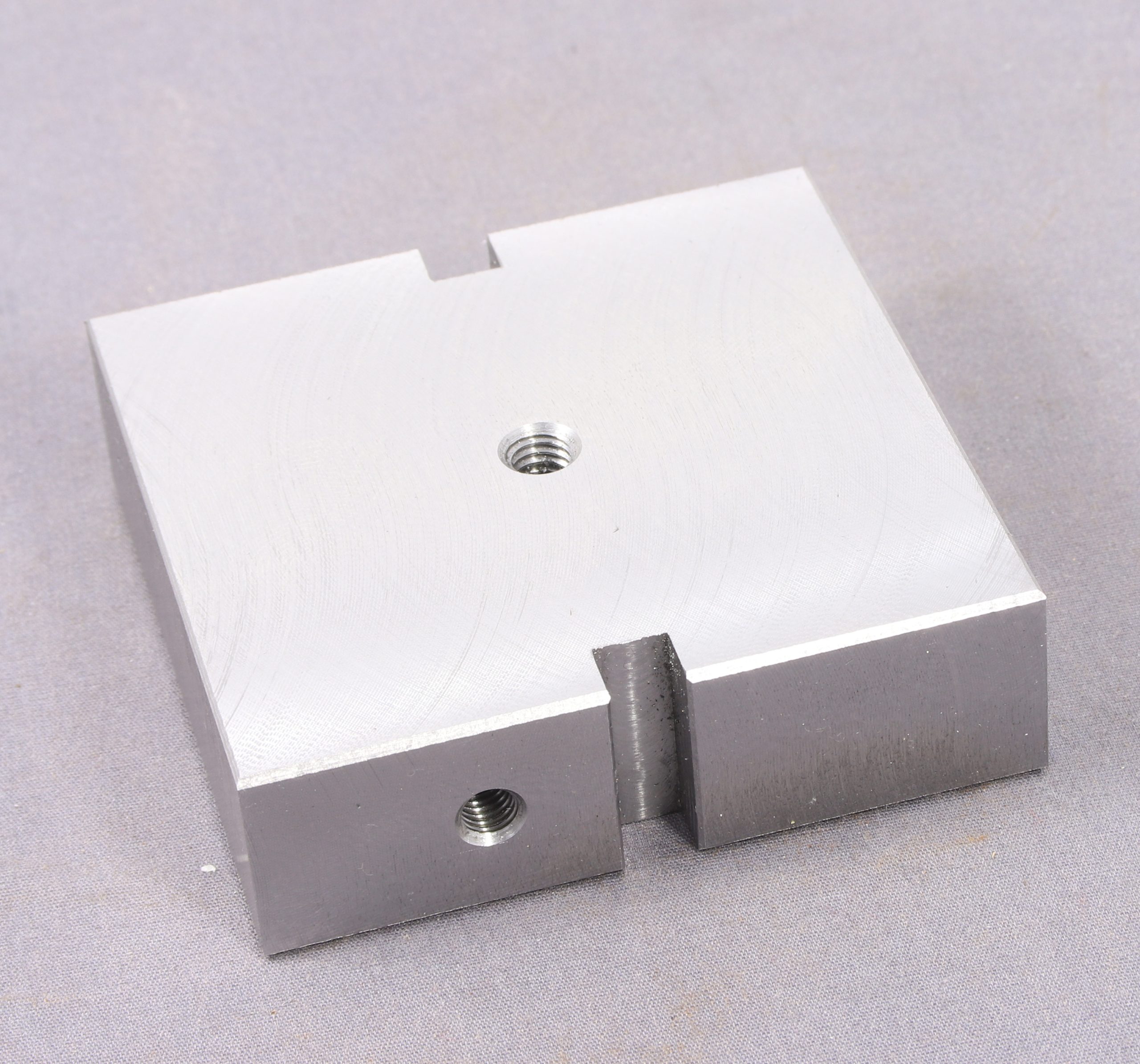
I dug it out and made a start on machining it yesterday afternoon. – Below is where I got to on preparing the base plate when I packed in for the day.
This morning I did more and this is where I got to by just after lunch. There is a still another groove to go into the base plate but I need to make another part (drill guide post) which will allow me to tie the position of the drill guide post to the V groove which is designed for drilling through the centre on the side of round stock.
Next up is the drill guide post but that will have to wait until I have had a coffee.
I have been a little quiet on the modelling front over the last couple of week because I have been fitting digital readouts to my lathe which became a bit more involved but worked out in the end. Needing something to test it out on I had a go at making some turnbuckle/shackles to secure the packing case to the wagon bed.
Staring with some 1.6mm rod (because I have lots) I drilled a 0.75mm hole 5mm down one and end then turned 3mm off the diameter for a length of 4mm. Then I filed hex flats on the full section and cut off at 5.5m beyond the start of the ‘nut’ This allowed me to reverse the pieces in the chuck, face off the end and repeat the process only this time I drilled right through before turning down 3mm x 4mm off that end giving me these
Turnbuckle Shackles in the making
I only managed three of them before it was time to go to our arts and crafts group again where I fed some 0.7mm wires through and twisted the ends into loops and added hooks.
This gave me these.
Turnbuckle Shackles
Here they are dangling from the packing case.
Turnbuckle Shackles
This morning I have turned another 4 centres and also soldered the gaps in the various links closed including the rings on the packing case itself as a pet hate of min is seeing chains 3 links etc that have open links.
I am most impressed by the ease of repeatability that the DRO on both carriage and cross slide allows.
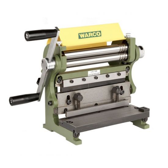
Way back in 2018 I bought a Warco Branded MiniFormit combination Guillotine, Bending Rolls and Folding brake.
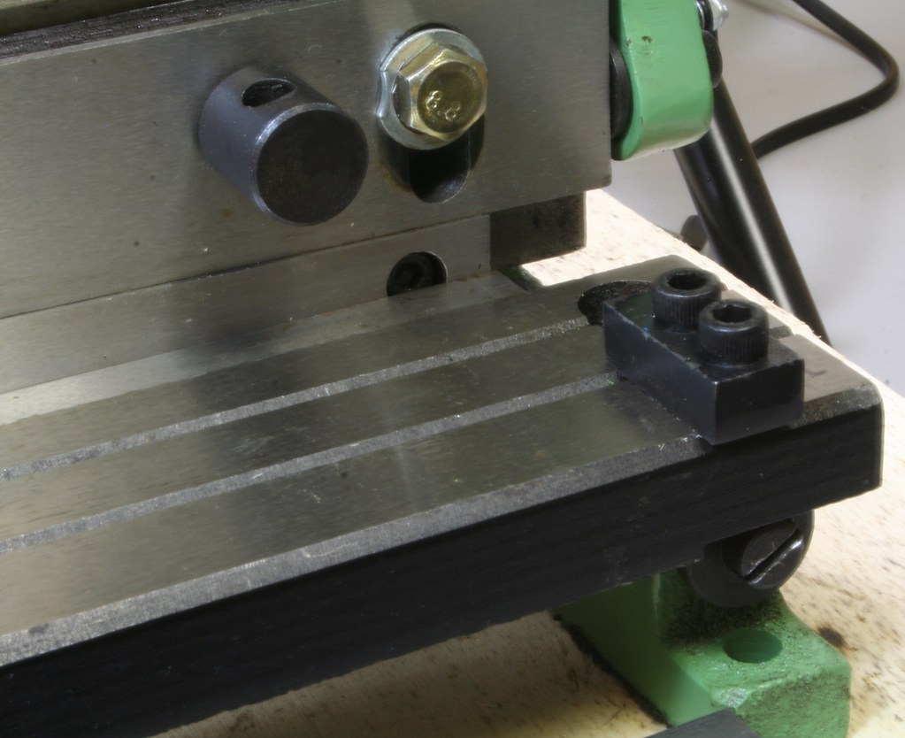
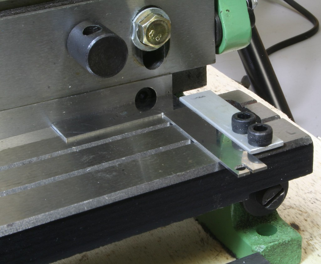
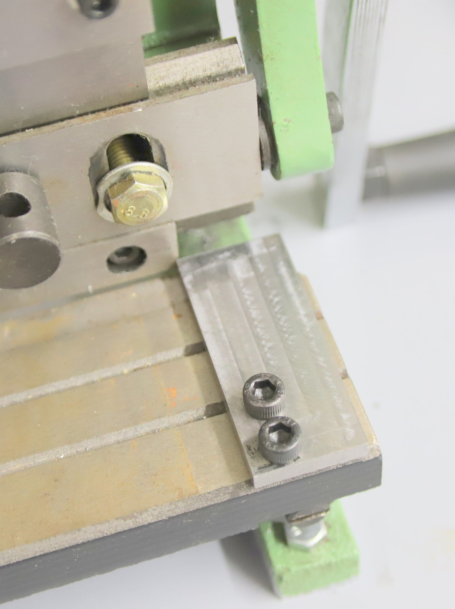
As it came I found that the guide which is the small dark block on the bottom right of the machine really wasn’t much use indeed it allowed the material being cut to pivot around it and thus not cut straight
So I replaced it with a strip of aluminium which was better but not great
Further improvements had me remove the spring loaded bar that is designed to hold the material flat but in reality it stops you from being able to see the cut line. I also made up a more robust block of steel to make a better guide
Since buying this back in 2018, I have mostly used the guillotine function, for cutting sheet brass or nickel and on occasions aluminium sheet recovered from shaving foam cans. I have also rarely used the rolling bars although having a similar set of rollers that are independant really does make it only used when I cannot be bothered to lift the rolling bars onto my workbench (they live underneath)
As sold the bumph claims that it will cut up to 1mm in steel and there is a bending brake function which apart from slipping a piece of crap sheet in as a test not long after buying it, I haven’t used it since or in any kind of ‘real’ situation.
Fast forward to the last few weeks. Knowing that the fitting of a DRO to may lathe would require the removal and modification of the swarf shield at the back of the lathe I bought in a couple of pieces of 1mm x 150mm x 500m (6″ x 18″) sheet steel. I chose the size based on the measurements taken from the existing swarf shield and knew that one of the pieces would just fit along the bottom of the shield to effectively push it 150mm further back. The other piece was planned for filling in any gaps left by the way that the existing shield had been cut out to fit around features on the back of the lathe.
Having finished fitting the Digital Readout scales to the lathe (to be reported in more detail in the relevant thread), my thoughts turned to the swarf shield. I had already drilled one of the pieces and bolted it to some aluminium angle to extend the bottom plate and then needed to fill in the gaps at the chuck end.
I measured the biggest gap which extended from the upper portion of the original shield forward to the rear of the lathe and then it required a right angle bend to fill the remaining gap just behind the chuck. I didn’t really fancy hacksawing it off so I decided to see if the manufacturers claim of it cutting 1mm sheet steel was true. I am pleased to say that it is.
Albeit, that I foolishly left some big bolts at the side of the guillotine and as the metal cut through. The force I was having to apply, sent the handle downwards at speed, trapping one of my fingers between the handle and one or more of the bolts. It made my eyes water a little but no real harm done.
Next I tried out the folding brake and again I was really pleased with the outcome. The first fold was relatively easy, but getting the bent sheet back out took a bit of jiggling.
For the last infill piece, I needed a much smaller piece which had a double bend. Cutting the smaller strip off was much easier and making the first bend was quite simple. But there wasn’t enough clearance for the bent material to feed into position for the second bend. I got around this by removing the anvil for the guillotine section which required unscrewing four caps screws. Two for the guide strip and the others actually holding the anvil in position.
Folded sheet metal
As an aside I have also used the guillotine to cut several pieces of an old aluminium number plate that had fallen off a vehicle and some kind person had tucked it in a fence (I suppose in the hope that the the person who lost it might see it and recover it). After seeing it tucked in the fence for a couple of years, I got fed up of looking it and decided to bin it. It was only as I was about to put it in the litter bin, that I realised that it was aluminium rather than plastic and would be useful as material at some point. During my fitting and refitting of scales to both lathe and mill I have used it to make several spacers. Although much thicker than 1mm, being aluminium, it cuts quite easily with the guillotine.


![[IMG]](https://live.staticflickr.com/65535/55146066002_4bb5dc48d2_h.jpg)
![[IMG]](https://live.staticflickr.com/65535/55147124323_5167fbc7eb_h.jpg)