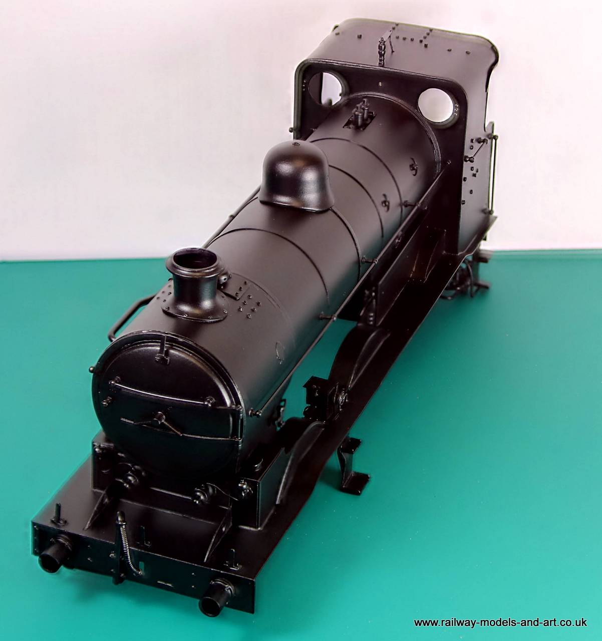
Then the world turned black. I had initially primed the tender body a couple of weeks ago when the sun last shone. I took the opportunity of sun here in the dales to get the body primed yesterday afternoon. I am greatly impressed with the finish of the Clostermans etch Primer. I have used it and the cellulose top coat before but only on loco chassis and you don’t really get the same effect. It’s also an absolute b***r to light properly for decent photos. These are my third attempt.
Gladiator J6 Loco Body PrimedGladiator J6 Loco Body PrimedGladiator J6 Loco Body PrimedGladiator J6 Tender Body PrimedGladiator J6 Tender Body PrimedGladiator J6 Tender Body PrimedGladiator J6 Tender Primed
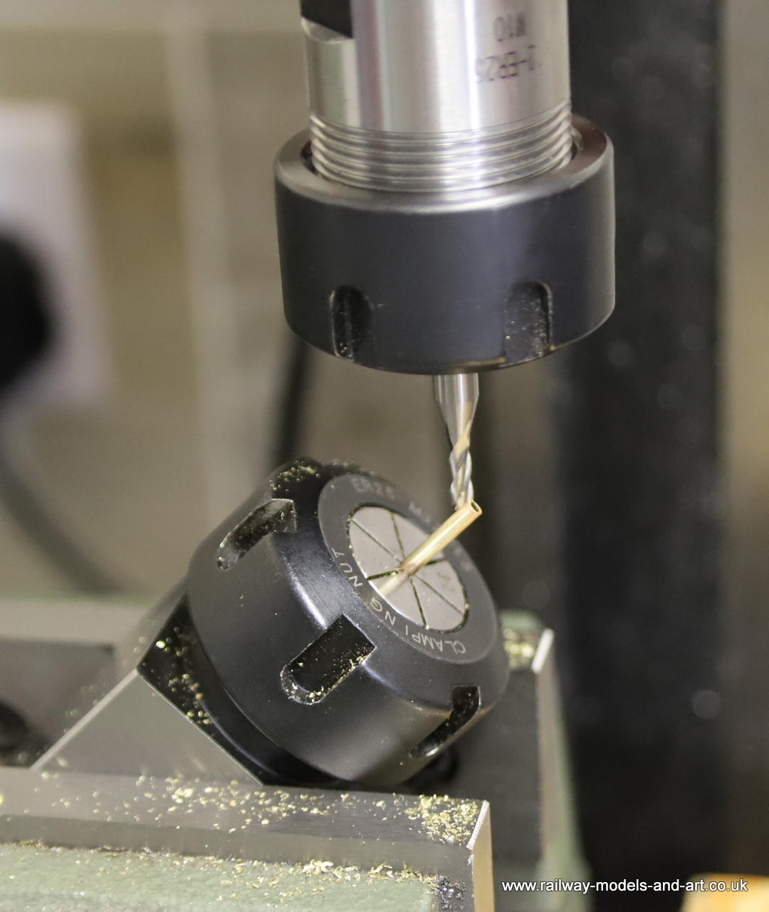
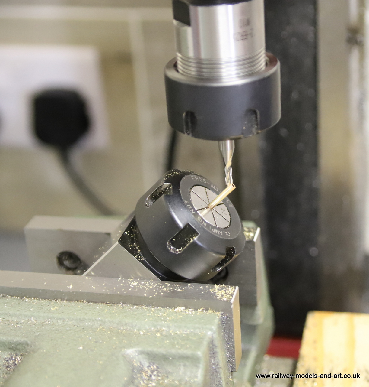
When posting the above about making up the vacuum pipe, I completely forgot to mention the making of the pipe elbows. In the past I have used a square file to file a V groove in some tube and then created the bend. This time I thought that I would have a go at doing it with the mill I set a collet block at 45 degrees using a set square and then used a 3mm end mill to cut the slot.
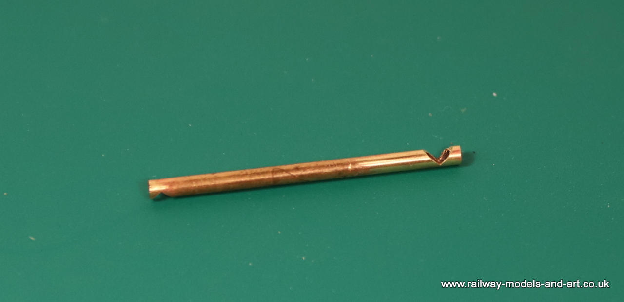
Milling a V cut out for a right angle bendMilling a V cut out for a right angle bendV cut out for a right angle bendright angle pipe bendRight angle Pipe bendsRight angle Pipe bends
Although I still need to finish of the chassis, the body and tender are pretty much complete, so I took the opportunity to return to this build and pipe up the injectors, and fit the vacuum pipe down the right hand side valence.
I had drilled the holes for the pipes and cut lengths of copper wire some time ago, then they were put aside.
Injector castings piped upInjector castings Pipes bent to shape and cut to lengthInjector castings Pipes bent to shape and cut to lengthInjector castings Pipes bent to shape and cut to length
The vacuum pipe was surprisingly difficult to photograph with it being so long.
Although I dressed the backhead a couple of weeks or so ago, I hadn’t managed to get it to fit into the cab before now because the stub of the whistle protruding through the cab roof stopped it from sliding in. One of those little few minute jobs that seem to take forever to get around to…. I finally got to it and the backhead now fits in place as if it was made for it.
Gladiator J6 Backhead fitted in the cabGladiator J6 Backhead fitted in the cabGladiator J6 Backhead fitted in the cab
After spending a week teaching myself 3D drawing, I was back
at the workbench today. I had originally planned to just turn a couple of
appropriately sized top hat bushes, file some flats on them where they come together
and job done. My recently acquired mill offered more possibilities to make
something that at least looks like the original even if it doesn’t attach in
the same way. This will be soldered to the cylinder front in between the slide
bars, instead of being suspended from a substantial bracket between the frames.
This is my first real item produced with the mill and I am
happy with how it turned out.
Milled Expansion link support bracketMilled Expansion link support bracketMilled Expansion link support bracketMilled Expansion link support bracket
This is where it will sit in between the slide bars on the cylinder front. I have added some fastenings to make it look as if it should be there, when it’s ultimately lost in the gloom between the frames.
Yesterday saw more progress on the motion for the J6, with the valves almost complete.
I still have the arms to make that connect the valve rockers with the expansion link etc. But I am pleased that I have got this far as I had hit a bit of a mental brick wall with concern that attempts at soldering on the valve rocker supports would result in them dissolving into individual parts again.
As happens often when procrastinating, I worried for nothing.
While I am distracted with outside jobs during the good
weather, I have been working on another of the key outstanding jobs that is
simple to pick up and put down. The back head/plate, is as I mentioned earlier
in the build, a GNR Boiler Back Plate set from LG Miniatures. It wasn’t quite
deep enough so I added a strip of thick brass along the bottom. Also missing
from the set as delivered, were the injectors. Laurie includes a layout drawing
in the set and it showed the missing injectors. An enquiry to Laurie had an apology
and a pair of injectors in the post.
I am not sure if they were from the GNR set or another more
generic pair but a little bit of scratch building had them looking the part. I
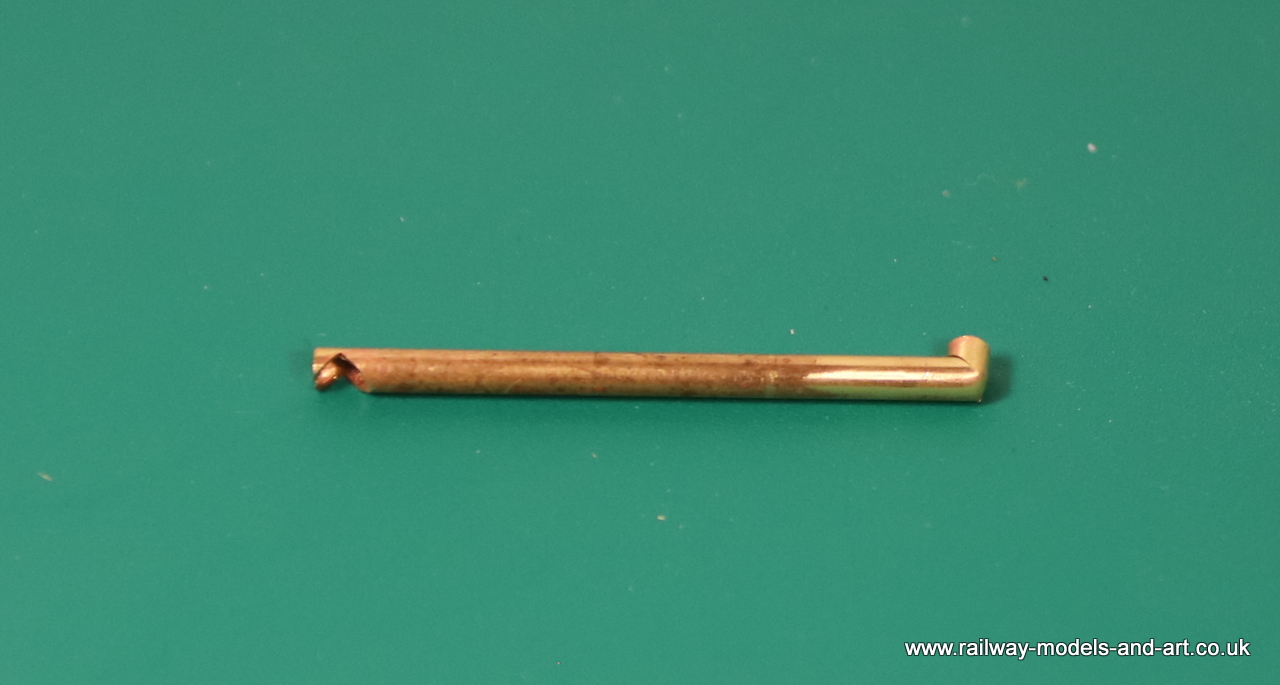
had to fabricate one of the levers for the right hand injector from a .9mm rod
with one end squashed and drilled out for the pin and then tapered with a file
in the mini drill (too small to old securely in the lathe).
In the end I only used one of the hand wheels from the set
because they came with cast stems on them and I wanted to fit them to the stem
already present on the castings so I used some cast hand wheels from the spares
box which had holes in the centres. Had I not had them to hand I would have cut
the stems of the castings and drilled them for the ones with the cast stems but
it would have been a bit tedious.
J6 BackheadJ6 Backhead
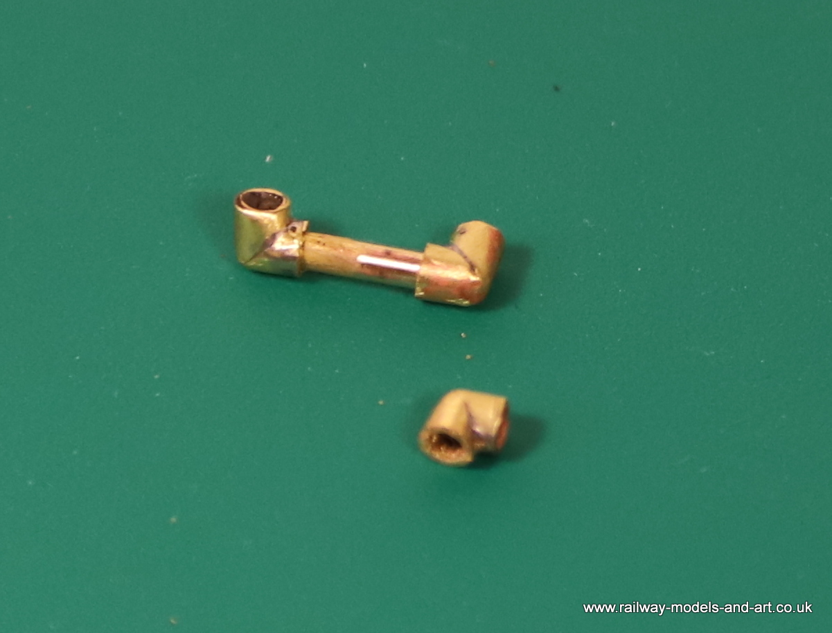
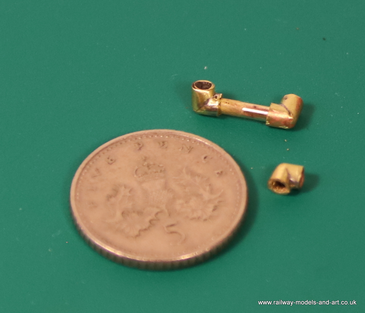
The GA showed some kind of inline valve down the right hand
side of the cab at the side of the back plate so I knocked one up from a couple
of bits of tube and a cast handwheel from the set.
J6 backhead – scratchbuilt inline valve
My apologies for the greenish tinge it’s reflections from
the green storage box that I propped it against for the photos.
Modelling time this last week has seen me back on the J6. I
have been making progress with the inside motion starting with soldering the
front of the slide bars to the cylinder front and then removing the motion
bracket and moving it backwards to match the drawing in order that it would then
clear the front horn guides.
Motion bracket and cylinder front joined together with the slide bars
Getting them square to each other was a little challenging
so I cut a couple of rectangles of 10thou sheet to set both the distance
between the cylinder front and the rear of the motion bracket and keep them
square at the same time. I used a couple of aluminium hair grips to hold them
in place while I soldered the ends of the slide bars to the motion bracket.
I still need to plot out and drill holes for the support
rods for the expansion links in the cylinder front.
I still need to plot out and drill the cylinder front for the support rods.
I have temporarily assembled most of the motion but I still
need to add the parts to the motion bracket which support and operate the valves.
Motion parts temporarily assembledMotion parts temporarily assembled
Having extended the clearance between the cylinder front and
the motion bracket so that the cylinder front sits in front of the horn guides,
I found that the slide bars still fouled the horn guides. T next task was to
reduce the depth of the front horn block in the lathe so my four-jaw chuck got
a turn. Because I only wanted to effectively face them off. I cheated a little
and fitted a short length of 3/16” silver steel into the tailstock, slipped a
bearing on and used that to quickly centre the four jaw.
Front Hornblocks reduced in depth on the lathe
The next task is to remove a section of the horn guides to clear
the slide bars.
Hornguides now need reducing to suit.
As soon as funds allow, I plan to buy a mill to compliment
the lathe and boy would a mill make this task easier. I can see now why Nick
plans his inside motion fitting as he builds the frames. A lesson learned for
the future! Onwards and upwards as they say.
One of the few remaining details to add to the body are the injectors which sit under the footplate tucked away behind the cab steps. From all the photos that I have of J6’s seeing what they actually look like is a real problem. Then I remembered that I had taken a few photos of the Injectors on the side of the preserved J52 while it lived at Shildon.
While I have a couple of good side views they don’t show the pipes and how they fit.
Then by pure chance I was looking through some photos that I took in the dark hall at York and found that I had indeed taken photos of each end
By cross referencing these with the end that’s visible on some better lit J6 photos I was able to confirm to my satisfaction that these are the same type of injector fitted to the J6 Now all I need to do is work out how to scale them to size – Despite taking quite a few shots at both locations none of them are side on allowing scaling from a known dimension.
Modelling time has been in a bit short supply so far this week but I have managed a few bits and pieces. The key one being, on the back of a delivery of a second set of globe lubricator castings for the J6, I got them fitted. I had to order some more because I have misplaced the first lot but I am sure that they will turn up in due course…
In between adding bits to the GCR Tank, After drilling and pinning the cranks which was thankfully uneventful. I cut out the axle in between the crank webs and refitted the connecting rods. I had to file a little of the sides of one one the connecting rods but very quickly all was rotating smoothly. So much so that I made a short video. Sadly my camera didn’t focus too well on my hands but you get the idea.
Today has been a brilliant day on quite a few fronts but the main one being that I successfully soldered the crank axle up without any issues.
I followed advice given to me by fellow modeller Nick Dunhill, which was to use Bakers Fluid as the flux to solder to the steel axle, to replace the piece of steel rod provided to line up the cranks and eccentric with a length of similar diameter brass rod which being more flexible allows the cranks and eccentrics to be squashed tighter together and positioned better. And finally, to wrap wet tissue around the eccentric sheaves to stop the soldered end coming adrift with the heat.
It couldn’t have gone any smoother, I spent some time making sure they were all lined up correctly and orientated against one of the flat edges of the axle end. I grip the other end in a biggish pin vice applied the Bakers fluids from a bulb type dropper and some short lengths of 180 solder curled slightly around the axle either side of the cranks then gently applied heat with the microflame until the solder flashed. While it was cooling I couldn’t resist moving the eccentrics slightly to make sure that they hadn’t become solid.
Next job is clean them up and then before cutting out the section of axle I think that I am going to drill and pin the cranks. I know that Nick doesn’t bother as they aren’t under any real load but I think that I will be belt and braces for this my first go.
A post on a few forums by Nick Dunhill on his build of a Rhymney Railway R class on preparing the eccentric sheaves couldn’t have been timelier.
I am just at that point so the night before last I made up a similar jig from a couple of bits of wood that I had on the bench and having consulted the GA for the length of the sheave I marked up and drilled a hole for the pin (a 0.8mm drill bit). Finally, I filed and soldered up the first sheave. Last night I managed a couple more.
Gladiator J6 Eccentric Sheaves Sizing JigInside Motion Eccentric Sheaves – for Gladiator J6Inside Motion Eccentric Sheaves – for Gladiator J6
Although I haven’t posted an update since before Christmas, I have been doing a bit here and there. Mostly this has been making the additional bits and pieces needed for the inside motion. The motion for the J6 differs from other versions of Stephenson’s motion in that it has four valves rather than the more usual two. There are two between the cylinders and two above them. Although I have the full LG Stephenson’s motion set, in the end I doubt that I will be able to use much more than the connecting rods, eccentric rods and the slide bars and cross heads. The other bits will go in the spares box for a future build.
Gladiator J6 Scratch Built Inside Motion Parts
The arms that fit to the lower linkages still need to be shortened to 5.5mm between hole centres.
The expansion links in the motion kit are a couple of millimetres longer than the GA and have a lug on one side which I would have to cut off for this particular application.
Gladiator J6 Inside Motion PartsGladiator J6 Inside Motion Parts
As I am making all the other parts to match the dimensions on the GA, I opted to make a pair of expansion links to match. Working on the theory that I always have the LG castings as a fall back, if my home brewed ones don’t fit for any reason.
Gladiator J6 Scratch Built Inside Motion PartsGladiator J6 Scratch Built Inside Motion Parts
I have been distracted for the last few days by teaching myself to draw in QCAD with a view to getting a few things etched. Before that I had made some progress on the rest of the inside valve gear.
Early in the week Tony Geary kindly pointed me at a photo of the inside valve gear on a 7 ½” gauge N2. Armed with this as a starting point I searched online and found a Facebook page chronicling the guy’s build. In his photo section I found loads of photos which have gone a long way to clarify in my mind what I was struggling to interpret from the GA.
I have a few photos of the full sized N2 valve gear which again are great for showing how things fit together above the slide bars but not below which is the area that I was struggling with. The build photos have clarified things now I just need to make up all the parts. Unfortunately, most of mine will need to be made from scratch as my spares box is nowhere near as comprehensive as Tony’s.
The sections are just resting in place for the photos I have a lot more to attach to both the motion plate and cylinder front before finally joining them.
After reading Tony’s struggle to fit all the inside motion in his J6 and observations made on a couple of forums by Ian Middleditch and Jim Snowdon. I decided to take the plunge and cut some new frame spacers to give me more room to play with. With the new spacers I have given myself a couple more millimetres. The downside is that I need to make a new motion bracket but I am sure it will be worth it.
Gladiator J6 new frame spacersGladiator J6 New frame spacers
Not a great deal to show for this week’s efforts on the J6.
I filled in the lightening holes in the front of the frames as the photo that I am working from doesn’t show any. I also cut away the bottom of the etched ashpan sides and fitted a representation of the bottom. This may need a bit of trimming to clear the gear wheel once finally fitted.
Gladiator J6 Ash Pan and Lightening HolesGladiator J6 Ash Pan
The rest of the time has been spent patiently filing the hornblocks, hornguides and the cranks to enable the cranks and eccentrics to fit between the centre hornguides and rotate freely.
Gladiator J6 Cranks and eccentricsGladiator J6 Cranks and eccentricsGladiator J6 Cranks and eccentrics
Due to the need to get the loco around 5’6” curves the frames are a bit narrower than they might have been if I had been building for myself.
Although it hasn’t been without its trials, I have made good progress this week and the bodywork is almost complete.
The left side handrail caused a few problems because the etched hole in the cab front, to which I had soldered the tube for the handrail proved to be slightly out of position. I am not sure whether it was a vagary of the hand drawn art work which I have then exacerbated as I have opened the hole with a broach or that my positioning of the boiler was slightly low.
To make it all line up I had to remove the stub of tube, fill the hole with brass rod and file flush then redrilling the hole slightly lower.
I also drilled the rims of the buffer stocks and inserted some scale hardware fittings the collar of the buffer stocks is quite small so it was a bit nerve wracking drilling with a 0.4mm drill bit, but it came out okay.
All the boiler fittings are soldered in place with the exception of the smokebox door which it just resting in place for the photos.
The front steps come with an interesting fold up support which makes them fairly rigid but before I had finished fitting the front one’s, I had managed to bend the rear ones so I soldered some 2x1mm bar behind them to give some strength.
The only things left to fit, are a pair of globe lubricators that sit on the front of the sandboxes either side of the smokebox. The reason that I haven’t fitted them yet is that I have lost them. I bought them at the same time as the backhead and some additional valve rods so I know that they are here somewhere but can I find them….
Of course, the moment I order some more to replace them they will pop out from where they are hiding so I am holding off for the minute.
Gladiator J6 Body almost completeGladiator J6 Body almost completeGladiator J6 Body almost completeGladiator J6 Body almost completeGladiator J6 WhistleGladiator J6 Body almost complete
This week has seen the lubricators fitted along with the firebox/ashpan sides. Then I fitted all the main components together and fitted it to the chassis. I needed to file a bit of the undersides at both ends to get the chassis to mate with the body. This is because I have used the narrowest frame spacer due to the need to get the loco around 5’ curves.
Gladiator J6 Body detailsGladiator J6 Body details
But it all fits now; I have just rested the chimney and dome on for the photo.
Lokking like a J6 now
I have also fitted the splashers and cab floor and fitted a couple of short lengths of tube through the front of the cab for the hand rails. On the GA and on internal shots of the C1 cab the right side handrail has a handwheel attached to it so I have added that too.
Gladiator J6 Cab details
Once I had the cab floor fitted I could determine the fit of the backhead. The Laurie Griffin castings although quoted as being for a J6 among other locos was a little short so I added a strip to the bottom. I suppose that makes a change from hacking bit of the sides to make them fit in cabs.
The latest bit of modelling madness is a couple of Wakefield mechanical lubricators.
The kit provides a couple of nice but generic lubricator castings which have a lid and a hand wheel but no pipework. The lubricators fitted to 64206 are a little unusual to my eyes at least in that the pipes all come out of the bottom whereas I am more used to then coming out at the bottom of one or both sides. Now I could have followed Tony’s example and gone for some Ragstone castings but where would be the fun in that.
Cutting out and drilling all the parts (18 each not including the pipes) was relatively easy the fun part was soldering them all together without it all collapsing in a heap.
Gladiator J6 Scratch Built Wakefield mechanical LubricatorsGladiator J6 Scratch Built Wakefield mechanical LubricatorsGladiator J6 Scratch Built Wakefield mechanical LubricatorsGladiator J6 Scratch Built Wakefield mechanical Lubricators
Not the easiest thing in the world to photograph but after taking the earlier shots I remembered the quite prominent wingnut on the top holding the lid shut.
Gladiator J6 Scratch Built Wakefield mechanical Lubricators
I made it from a 16 ba cheese head screw with the head squashed in a pair of pliers and then filed to shape.